


8
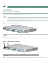
Note Slots 2 and 3 accept VICs only. These slots have a small metal tab on the right side that interferes with a similar
tab on WICs, preventing the insertion of WICs by mistake.
Step 6 Tighten the screws that are on the card.
Voice Port Verification
When the router is connected to a PC and you are running the command-line interface, as described in the “Connect a PC to
the Router Console Port” section, you can enter the show voice port command to identify the port numbers of voice interfaces
installed in your router:
Router# show voice port slot-number/port-number
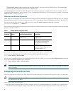
As an example of voice port numbering, if you install VICs in both slot 1 and slot 2 of the router, the ports in each of these slots
would be numbered as follows:
Slot 1—1/0 and 1/1
Slot 2—2/0 and 2/1
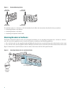
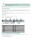
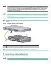
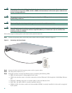
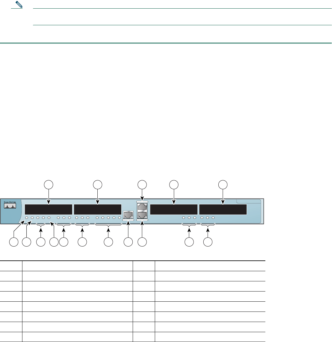
Figure 7 shows the Cisco 1760 router front panel and slot numbering.
Figure 7 Cisco 1760 Router Front Panel
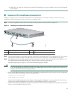
6 Connecting the Router to Your Local Network
The router is connected to your local Ethernet network through the yellow 10/100 Ethernet port. You must provide the
following items for this connection:
• A straight-through, RJ-45-to-RJ-45 Ethernet cable
• A 10/100-Mbps Ethernet hub or switch
1
WIC/VIC Slot 0
9
Ethernet Port
2
WIC/VIC Slot 1
10
Ethernet LEDs
3
Console Port
11
Slot 1 LEDs
4
VIC Slot 2
12
Slot 0 LEDs
5
VIC Slot 3
13
MOD OK LED
6
Slot 3 LEDs
14
PVDM 0/1 OK LEDs
7
Slot 2 LEDs
15
Router OK LED
8
Auxiliary Port
16
Power LED
Cisco 1700 Series
10/100 ETHERNET
AUX
CONSOLE
PWR OK PVDM 0
OK
PVDM 1
OK
MOD
OK
ACT COL FDX 100 LINKSLOT 0
OK
0 1 SLOT 1
OK
0 1 SLOT 2
OK
0 1 SLOT 3
OK
0 1
60906
1 2 3
10
4 5
16 15 13
9 814 12 11 7 6
THESE SLOTS ACCEPT ONLY VOICE INTERFACE CARDS