


Chapter 5 Troubleshooting the System Hardware
Power-On Self Test (POST)
5-16
Cisco Wide Area Virtualization Engine 274 and 474 Hardware Installation Guide
OL-17739-01
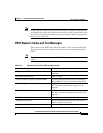
Interpreting POST Diagnostic Front Panel LEDs and Beep Codes
This section covers the front panel LED codes as well as the beep codes that may
occur before or during POST that do not necessarily have an error code or text
message associated with them.
Table 5-11 lists the recommended actions in the order in which they should be
performed.
Caution There are no customer-replaceable components inside your WAVE-274 or
WAVE-474 appliance. All faulty components can only be replaced by a qualified
service technician. Once you have identified a faulty component, contact the
Cisco Technical Assistance Center (TAC).
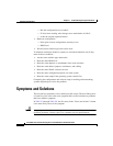
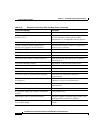
Network Server Mode Active and No Keyboard
Attached
Keyboard failure while Network Server Mode
enabled.
Parity Check 2 Parity RAM failure.
System will not boot without fan CPU fan not installed or disconnected in VSFF
chassis.
Table 5-10 Diagnostic Front Panel LEDs and Beep Codes (continued)
Control Panel Message Description
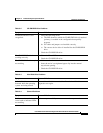
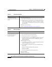
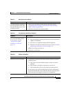
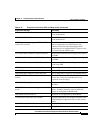
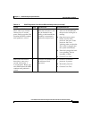
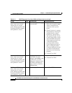
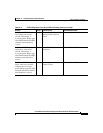
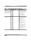
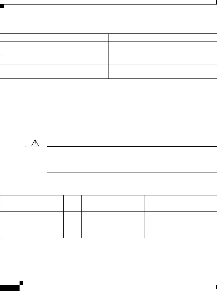
Ta b l e 5-11 POST Diagnostic Front Panel LEDs and Beep Codes
Activity Beeps Possible Cause Recommended Action
Green Power LED On. None Computer on. None
Green Power LED flashes
every two seconds.
None Computer in Suspend to
RAM mode (some models
only) or normal Suspend
mode.
None required. Press any key or
move the mouse to wake the
computer.