1-19
Catalyst 2960-S Switch Hardware Installation Guide
OL-19732-04
Chapter 1 Product Overview
Rear Panel
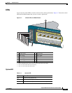
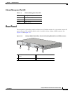
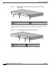
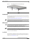
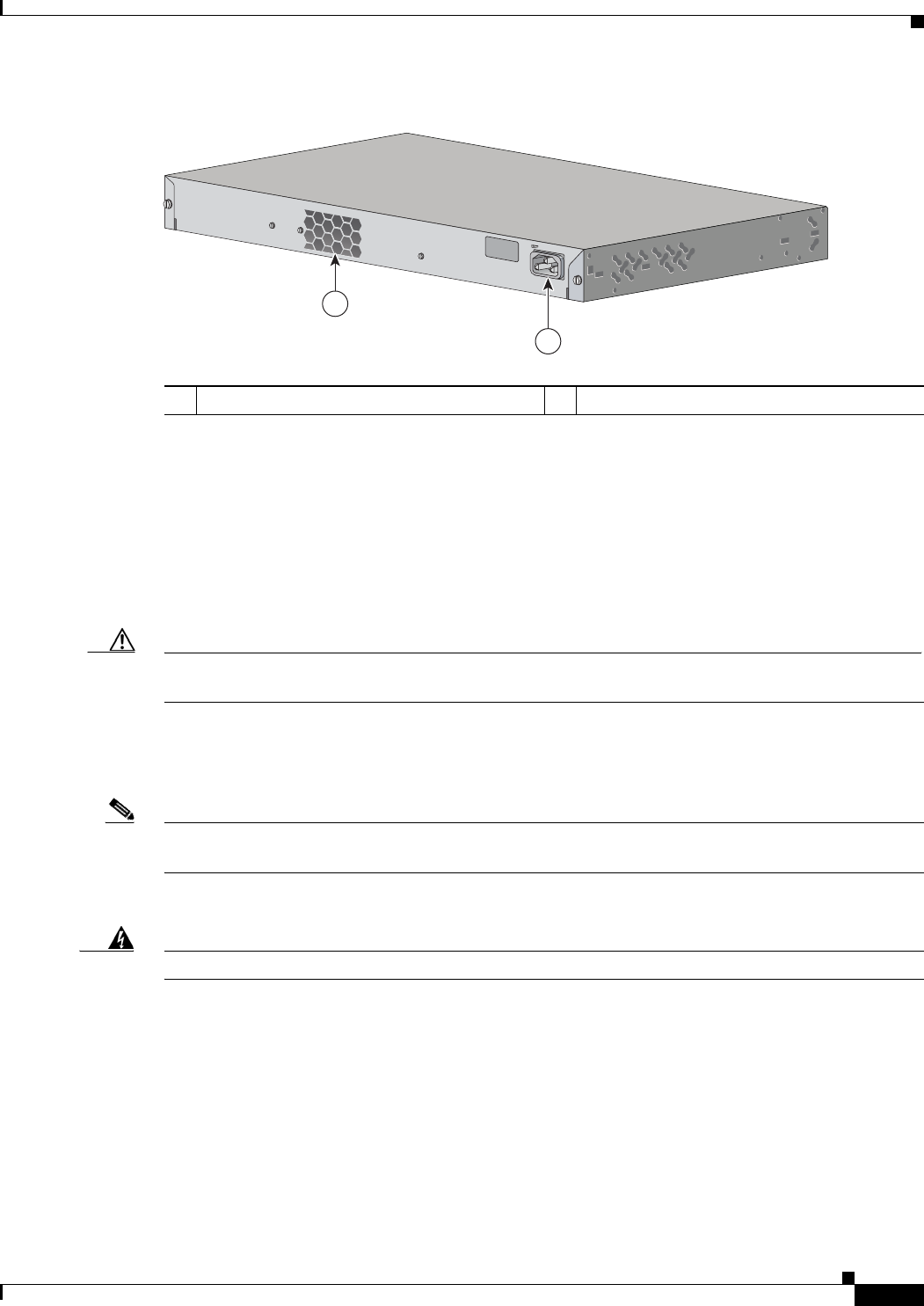
Figure 1-13 Catalyst 2960-S Switch Rear Panel without an RPS connector
FlexStack Ports
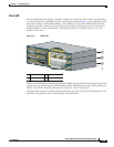
The stacking-capable switch models support stacking with the optional stack kit. It has the FlexStack
module (hot-swappable) to insert in the slot in the switch rear panel, and a 0.5-meter FlexStack cable to
connect the FlexStack module ports.
For FlexStack module installation, see “Installing the FlexStack Module” section on page 2-7. For stack
cabling, see “Connecting the FlexStack Cables” section on page 2-17.
Caution Use only approved cables, and connect only to other Catalyst 2960-S switches. Equipment might be
damaged if connected to other nonapproved Cisco cables or equipment.
RPS Connector
Note RPS is not supported on the Catalyst 2960S-F48FPS-L, 2960S-F48LPS-L, 2960S-F24PS-L,
2960S-F48TS-L, 2960S-F24TS-L, 2960S-F48TS-S, and 2960S-F24TS-S switches.
The Cisco RPS 2300 (model PWR-RPS2300) supports the Catalyst 2960-S switch.
Warning
Attach only the following Cisco RPS model to the RPS receptacle: RPS2300.
Statement 370
Connect the switch and the redundant power system to different AC power sources.
Use this cable for the RPS: CAB-RPS2300-E.
Cisco RPS 2300
The Cisco RPS 2300 is a redundant power system that can support six external network devices and
provide power to one or two failed devices at a time. It senses when the internal power supply of a
connected device fails and provides power to the failed device, preventing loss of network traffic. For
information, see the
“Related Publications” section.
1 Fan exhaust 2 AC power connector
RATING
100-240~
12-6A, 50-60Hz
344242
1
2


