


42-85
Catalyst 3750-X and 3560-X Switch Software Configuration Guide
OL-21521-01
Chapter 42 Configuring IP Unicast Routing
Configuring Multi-VRF CE
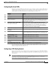
Multi-VRF CE Configuration Example
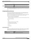
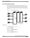
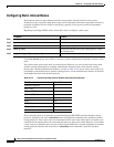
Figure 42-7 is a simplified example of the physical connections in a network similar to that in
Figure 42-6. OSPF is the protocol used in VPN1, VPN2, and the global net
work. BGP is used in the CE
to PE connections. The examples following the illustration show how to configure a switch as CE
Switch A, and the VRF configuration for customer swit
ches D and F. Commands for configuring CE
Switch C and the other customer switches are not included but would be similar. The example also
includes commands for configuring traffic to Switch A for a Catalyst 6000 or Catalyst 6500 switch acting
as a PE router.
Figure 42-7 Multi-VRF CE Configuration Example
Configuring Switch A
On Switch A, enable routing and configure VRF.
Switch# configure terminal
Enter configuration commands, one per line. End with CNTL/Z.
Switch(config)# ip routing
Switch(config)# ip vrf v11
Switch(config-vrf)# rd 800:1
Switch(config-vrf)# route-target e
xport 800:1
Switch(config-vrf)# route-target i
mport 800:1
Switch(config-vrf)# exit
Switch(config)# ip vrf v12
Switch(config-vrf)# rd 800:2
Switch(config-vrf)# route-target e
xport 800:2
Switch(config-vrf)# route-target i
mport 800:2
Switch(config-vrf)# exit
Switch A
Switch D
VPN1
VPN2
CE1
Global network
208.0.0.0
Fast
Ethernet
8
Gigabit
Ethernet
1
101386
PE CE2
Switch E
108.0.0.0
Fast
Ethernet
7
Switch F
118.0.0.0
Fast
Ethernet
11
Switch G
168.0.0.0
Fast
Ethernet
3
VPN1
VPN2
Global network
Switch H
Switch J
Switch K
CE = Customer-edge device
PE = Provider-edge device
Switch B Switch C