


16
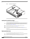
Installing Power Supplies in Cisco 3631 Routers
78-13818-03
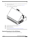
Electrical Connections for Cisco 3631 Routers
Warning
This unit is intended for installation in restricted access areas. A restricted access area is where
access can only be gained by service personnel through the use of a special tool, lock and key, or
other means of security, and is controlled by the authority responsible for the location. To see
translations of the warnings that appear in this publication, refer to the Regulatory Compliance
and Safety Information document that accompanied this device.
Warning
Before performing any of the following procedures, ensure that power is removed from the DC
circuit. To ensure that all power is OFF, locate the circuit breaker on the panel board that services
the DC circuit, switch the circuit breaker to the OFF position, and tape the switch handle of the
circuit breaker in the OFF position. To see translations of the warnings that appear in this
publication, refer to the Regulatory Compliance and Safety Information document that
accompanied this device.
Warning
This product relies on the building’s installation or power supply for short circuit (overcurrent)
protection. Ensure that a Listed and Certified fuse or circuit breaker no larger than 60 VDC, 15A is
used on all current-carrying conductors. To see translations of the warnings that appear in this
publication, refer to the Regulatory Compliance and Safety Information document that
accompanied this device.
Caution If you connect parallel dual 48V DC power sources, both sources must be the same polarity. Do not
connect –48V and +48V sources to a Cisco 3631 router. Opposite-polarity sources connected in
parallel will damage the power supply.
Note The installation must comply with the 2002 National Electric Code (NEC) and other applicable
codes.
Warning
This product is intended for use with copper conductors only.
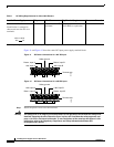
Wire and Terminal Requirements
A Cisco 3631 router with a DC-input power supply requires copper wire, size AWG 18 (1.0 mm
2
), for
the power connections, and it requires a NEBS-compliant ground connection on the chassis, using size
AWG 6 (minimum 13 mm
2
) copper wire.
The connections must be made using crimp-type ring terminals, Molex part number 19073-0009
(individual), 19073-0019 (on tape and reel), or equivalent.
You can connect a single DC power source to either the A input or the B input. If there are parallel dual
power sources, connect one source to the A input and one source to the B input; both sources must be
the same polarity (–48V or +48V). A NEBS-compliant chassis ground connection is required with both
single source and parallel dual sources.