


32 4030802 Rev A
Front Panel LED Status Indicator Functions
Front Panel LED Status Indicator Functions
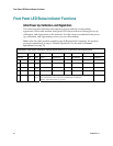
Initial Power Up, Calibration, and Registration
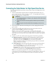
The following chart illustrates the sequence of steps and the corresponding
appearance of the cable modem front panel LED status indicators during power-up,
calibration, and registration on the network. Use this chart to troubleshoot the power
up, calibration, and registration process of your cable modem.
Note: After the cable modem completes step 8 (Registration Complete), the modem
proceeds immediately to step 9, Normal Operations. See the table in Normal
Operations (on page
33).
Front Panel LED Status Indicators During Initial Power-Up, Calibration, and Registration
Step 1 2 3 4 5 6 7 8
Front Panel
Indicator
Power
Up
Self
Test
Downstream
Scan
Downstream
Signal Lock
Ranging Requesting
IP Address
Registering Registration
Complete
1 POWER
On On On On On On On On
2 DS
Blinks On
1 sec
Blinks On On On On On
3 US
Blinks On
1 sec
Off Off Blinks On On On
4 ONLINE
Blinks On
1 sec
Off Off Off Off Blinks On
5 LINK
Off On
1 sec
Off - When no devices are connected to the Ethernet or USB ports
On - When devices are connected to the Ethernet or USB ports
Blinks - When data activity is present
On