


Index
IN-5
Catalyst 4500 E-Series Switches Installation Guide
OL-13972-01
S
serial numbers 5-18
shipping instructions B-1
show port command D-8
show system command 4-8
site planning
checklist 2-11
slots
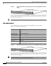
Catalyst 4503-E switches (figure) 1-2
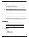
Catalyst 4506-E switches (figure) 1-5
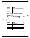
Catalyst 4507 switches (figure) 1-9, 1-13
specifications
Catalyst 4503-E switches (table) A-1
Catalyst 4506-E switches (table) A-2
Catalyst 4507 switches (table) A-3, A-5
startup
troubleshooting 5-2
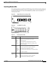
STATUS LED
description (table) 1-22
Status LEDs
supervisor engines D-3
Supervisor Engine IV
front panels (figure) 1-20, 1-21
supervisor engines
Catalyst 4503-E switches 1-3
Catalyst 4506-E switches 1-6
Catalyst 4506 switches 1-10, 1-14
console ports D-4
description 1-16
LEDs (table) 1-22
slot locations 1-2, 1-5, 1-9, 1-13
specifications (table) A-14
Supervisor Engine V-10GE
front panels (figure) 1-21
switching modules
Catalyst 4503-E supported 1-3
Catalyst 4506-E supported 1-6
Catalyst 4507R supported 1-11
Catalyst 4510R supported 1-15
LEDs D-7
switch load indicators D-3
T
TAC
contacting 5-18
temperature
Catalyst 4503-E switches A-1
Catalyst 4506-E switches A-2
Catalyst 4507 switches A-3, A-5
terminal-emulation software C-2
troubleshooting 5-4
boot process 5-2
fan assemblies 5-6
power supplies 5-4
startup 5-2
U
uplink ports
description 1-22
UTILIZATION LEDs
description (table) 1-22
V
voltage
specifications A-8, A-10
W
weight
Catalyst 4503-E switches (table) A-2
Catalyst 4506-E switches (table) A-3
Catalyst 4507 switches (table) A-4, A-5