


4-14
Catalyst 4500 E-Series Switches Installation Guide
OL-13972-01
Chapter 4 Removing and Replacing FRUs
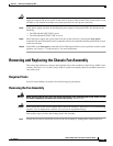
Removing and Replacing the Chassis Fan Assembly
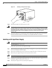
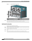
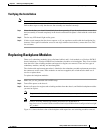
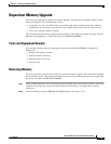
Figure 4-17 Catalyst 4506-E System Fan Assembly
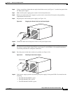
Step 2 Grasp the fan assembly with both hands and pull it outward; gently move it side to side if necessary to
unseat it from the backplane. Slide it out of the chassis and place it in a safe place.
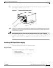
Installing the Fan Assembly
Follow these steps to install the new fan assembly:
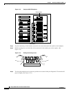
Step 1 Hold the fan assembly with the fans facing to the right.
Step 2 Place the fan assembly into the fan assembly bay so it rests on the chassis, and then lift the fan assembly
up slightly, aligning the top and bottom guides.
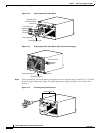
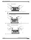
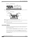
Step 3 Slide the fan assembly into the chassis until the two captive installation screws make contact with the
chassis.
Step 4 Using a screwdriver, tighten the two captive installation screws by turning them clockwise.
1 Captive installation screws 2 Fan assembly
231372
4
5
0
6
2
1