


4-11
Catalyst 4500 E-Series Switches Installation Guide
OL-13972-01
Chapter 4 Removing and Replacing FRUs
Removing and Replacing the Power Supply
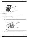
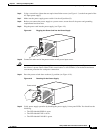
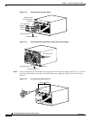
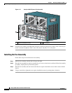
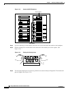
Step 7 Grasp the power supply handle with one hand. Place your other hand underneath as you slowly pull the
power supply out of the bay (see
Figure 4-16).
Figure 4-16 Handling a DC-Input Power Supply
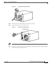
Step 8 If the bay is to remain empty, install a blank power supply filler plate over the opening and secure it with
the mounting screws. This protects the inner chassis from dust and prevents accidental contact with live
voltage at the rear of the bay.
Warning
Blank faceplates and cover panels serve three important functions: they prevent exposure to
hazardous voltages and currents inside the chassis; they contain electromagnetic interference (EMI)
that might disrupt other equipment; and they direct the flow of cooling air through the chassis. Do not
operate the system unless all cards, faceplates, front covers, and rear covers are in place.
Statement
1029
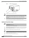
Installing a DC-Input Power Supply
This section describes how to install a DC-input power supply.
Required Tools
You will need the following tools to perform this procedure:
• A Phillips screwdriver
• A 10-mm wrench/socket
• Connectors and wire for the DC circuit or circuits
79163