


Chapter 2 Site Planning
Grounding Requirements
2-4
Cisco Catalyst 4900M Switch Installation Guide
78-18350-01
EMI Recommendations
Follow these guidelines when setting up the site wiring. When planning the
location of the new system, consider electromagnetic interface (EMI), the
distance limitations for signaling, and connector compatibility.
When wires are run for any significant distance in an electromagnetic field, radio
frequency interference (RFI) can occur between the field and the signals on the
wires.
• Bad plant wiring can result in radio frequency interference.
• Strong EMI, especially when caused by lightning or radio transmitters, can
destroy the signal drivers and receivers in the switch and can create an
electrical hazard by conducting power surges through lines and into
equipment.
Note To predict and remedy strong EMI, you might need to consult RFI experts.
Power Requirements and Heat Dissipation
The power requirements might be useful for planning the power distribution
system needed to support the switches. Heat dissipation is an important
consideration for sizing the air-conditioning requirements for an installation.
Refer to
Appendix A, “Specifications,” for the power and heat ratings for a
Catalyst 4900M switch.
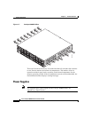
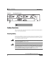
Grounding Requirements
Grounding is recommended on all AC or DC installations, using only approved
copper connectors. Attach the provided two hole ground lug to the chassis using
M4x 8mm bolts and then to the central office (CO) or other interior ground system
with number 6
AWG wire. The grounding connector is on the rear of the chassis,
as shown in
Figure 2-1.