


3-15
Cisco Catalyst 4900M Switch Installation Guide
78-18350-01
Chapter 3 Installing the Switch
Optical Connections
• The PS1 or PS2 LED is off when the power supply is not connected to a power
source.
From the system console, enter the show power command to display the power
supply and system status. For more information on this command, see the
command reference publication for your software release.
If the LEDs or show power command indicate a power or other system problem,
see
Chapter 4, “Troubleshooting the Installation,” for troubleshooting
information.
Optical Connections
The Cisco 4900M switch has up to 24 ports that can be configured with X2
modules with SC connectors. Module types supported are documented at:
http://www.cisco.com/en/US/products/hw/modules/ps5455/products_device_sup
port_table09186a00803857e7.html
Generic connection instructions for the X2 modules are at:
http://www.cisco.com/en/US/docs/interfaces_modules/transceiver_modules/inst
allation/note/78_16705.html
Installation documentation for Cisco TwinGig converter modules can be found at:
http://www.cisco.com/en/US/docs/switches/lan/catalyst3750e_3560e/hardware/i
nstall/notes/1757202.html
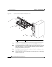
Configurable Modules
All Catalyst 4900M modules support hot swapping, which lets you install,
remove, replace, and rearrange switching modules without turning off the system
power. When the system detects that a switching module has been installed or
removed, it runs diagnostic and discovery tests automatically, acknowledges the
presence or absence of the module, and resumes system operation with no
operator intervention.