


3-13
Cisco Catalyst 4900M Switch Installation Guide
78-18350-01
Chapter 3 Installing the Switch
Connecting DC Power to the Catalyst 4900M Switch
If the LEDs or show power command indicate a power or other system problem,
see
Chapter 4, “Troubleshooting the Installation,” for troubleshooting
information.
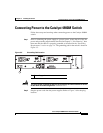
Connecting DC Power to the Catalyst 4900M Switch
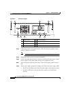
Follow these steps and warnings when connecting DC power to the
Catalyst
4900M switch:
Warning
Before performing any of the following procedures, ensure that power is
removed from the DC circuit.
Statement 1003
Warning
This unit is intended for installation in restricted access areas. A restricted
access area can be accessed only through the use of a special tool, lock and
key, or other means of security.
Statement 1017
Warning
This product requires short-circuit (overcurrent) protection, to be provided as
part of the building installation. Install only in accordance with national and
local wiring regulations.
Statement 1045
Warning
Hazardous voltage or energy may be present on DC power terminals. Always
replace cover when terminals are not in service. Be sure uninsulated
conductors are not accessible when cover is in place.
Statement 1075
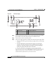
Step 1 Prior to connecting the power supply to a power source, ensure that all of the site
power and grounding requirements described in
Chapter 2, “Site Planning,” have
been met and the chassis is properly grounded as described in the “Grounding
Requirements” section on page 2-4.
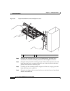
Step 2 Remove the safety cover from the power terminal.
Step 3 Connect the power supply ground terminal to earth ground.