


Chapter 3 Installing the Switch
Connecting DC Power to the Catalyst 4900M Switch
3-14
Cisco Catalyst 4900M Switch Installation Guide
78-18350-01
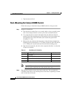
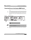
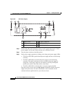
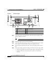
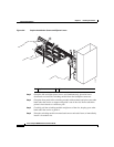
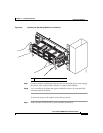
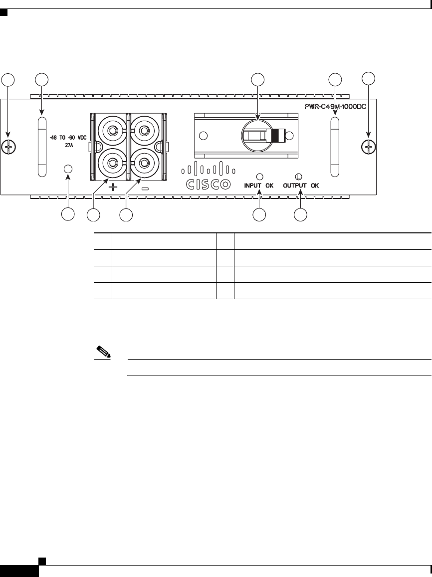
Figure 3-7 DC Power Supply
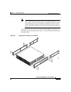
Step 4 Connect the positive and negative power cables into the power supplies using a
number 2 Phillips screwdriver.
Note The DC power cables may use AWG #10 to AWG #12 wire.
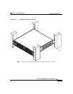
Step 5 Replace the safety cover over the power terminals.
Step 6 Connect the other end of the power cables to an DC-power input source. If both
power supplies will be used, make sure they are on different circuits.
Step 7 Turn on the power from the power source. Turn the DC supply on/off switch to
ON.
Step 8 Verify power supply operation by looking at the front panel power supply LEDs:
• The PS1 or PS2 LED is green when the power supply is functioning normally.
• The PS1 or PS2 LED is red when the power supply is not functioning
normally.
1 Captive screw 5 Positive terminals
2 Handle 6 Negative terminals
3 On/off switch 7 INPUT OK LED
4 Ground terminal 8 OUTPUT OK LED
232130
2 23
1
1
7
4
8
5 6