


1-9
Installation and Upgrade Guide for Cisco Unified MeetingPlace Audio Server 6.x
OL-13417-01
Chapter 1 Preparing to Install the Cisco Unified MeetingPlace 8100 Series Hardware
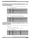
Wiring Requirements for Customer-Supplied Connectors—U.S., Canada, and Hong Kong
Wiring Requirements for Customer-Supplied Connectors—U.S.,
Canada, and Hong
Kong
Table 1-3 and Table 1-4 describe wiring requirements for customer-supplied RJ-48 connectors.
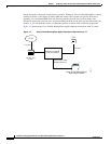
To identify the pins, hold the RJ-48 connector as if you are going to plug it in with the tab down. Pin 1
is on the left.
If transmit and receive need to be reversed, also reverse the pins. See Table 1-4.
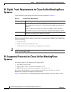
Wiring Requirements for Customer-Supplied Connectors—U.K.,
Singapore, and India
For the E1 card, the connection from the network interface to the network can be one of the following
types:
• RJ-45connector.
• SMB coaxial connectors with SMB/BNC adapters.
Table 1-5 describes wiring requirements for customer-supplied RJ-45 connectors.
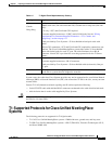
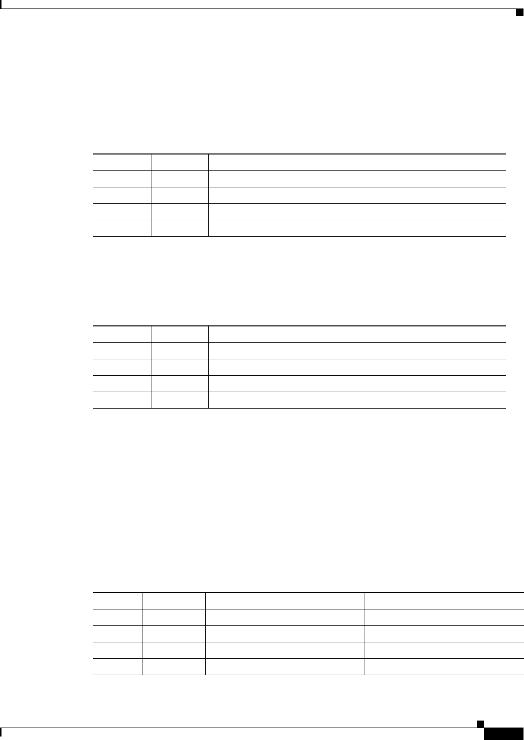
Ta b l e 1-3 Wiring of RJ-48 Connectors
Pin Name Description
1 T1 Cisco Unified MeetingPlace received signal - tip
2 R1 Cisco Unified MeetingPlace received signal - ring
4 T Cisco Unified MeetingPlace outgoing signal - tip
5 R Cisco Unified MeetingPlace outgoing signal - ring
Ta b l e 1-4 Wiring of RJ-48 Connectors When Transmit/Receive Is Reversed
Pin Name Description
1 T Cisco Unified MeetingPlace outgoing signal - tip
2 R Cisco Unified MeetingPlace outgoing signal - ring
4 T1 Cisco Unified MeetingPlace received signal - tip
5 R1 Cisco Unified MeetingPlace received signal - ring
Ta b l e 1-5 Wiring of RJ-45 Connectors
Pin Signal Description Direction
1 LRT Receive +ve (tip) Input
2 LRR Receive –ve (ring) Input
4 LTT Transmit +ve (tip) Output
5 LTR Transmit –ve (ring) Output