


2-14
Installation and Upgrade Guide for Cisco Unified MeetingPlace Audio Server 6.x
OL-13417-01
Chapter 2 Installing the Cisco Unified MeetingPlace 8100 Series Hardware
Connecting the Cables to the Cisco Unified MeetingPlace 8100 Series
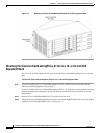
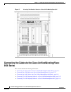
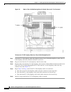
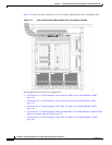
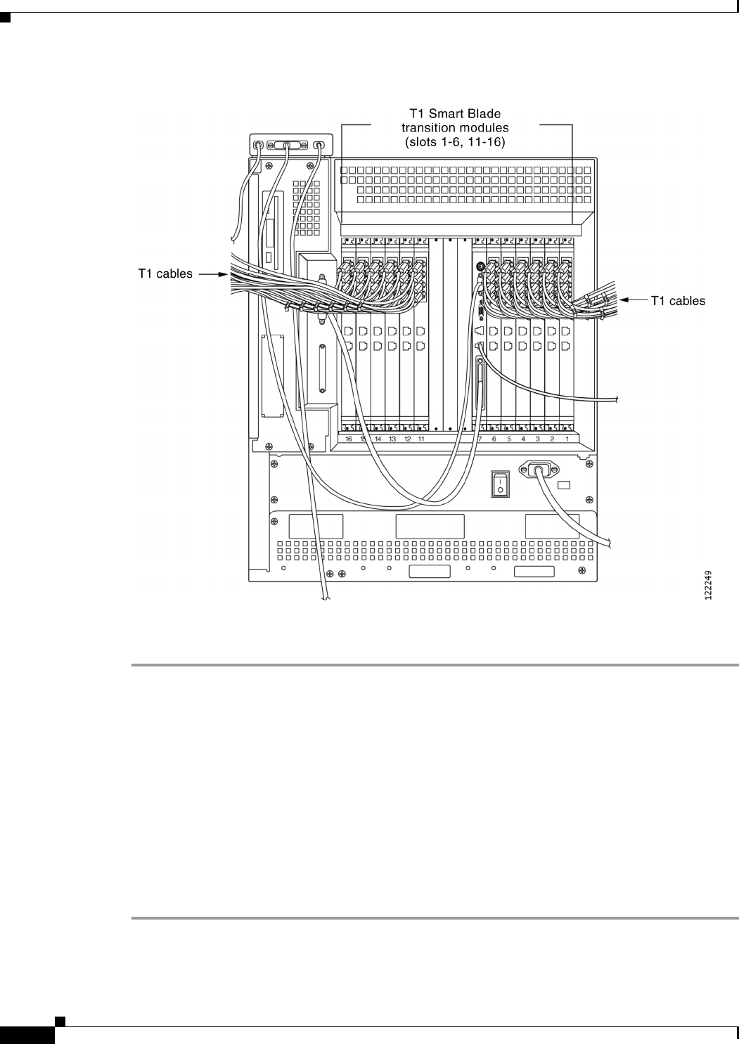
Figure 2-9 Back of Cisco Unified MeetingPlace 8112 Audio Server with T1s Connected
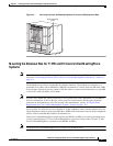
To Connect the T1 CAS Telephony Cables for a Cisco Unified MeetingPlace 8112
Step 1 Locate the T1 CAS telephony cables that shipped with the Cisco Unified MeetingPlace system. Each T1
CAS telephony cable has an RJ-48 connector on each end.
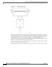
Step 2 Plug one end of the first T1 CAS telephony cable into the socket.
Step 3 Plug the other end of the first T1 CAS telephony cable into the T1 Smart Blade transition module in the
back of the Cisco Unified MeetingPlace 8112. Place the first T1 CAS telephony cable in the top
connector slot. (See
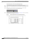
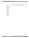
Table 2-2.)
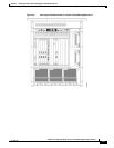
Step 4 Repeat Step 2 and Step 3 until all the T1 CAS telephony cables are connected:
a. Place the second T1 CAS telephony cable in the next connector slot moving down.
b. Place the third T1 CAS telephony cable in the third connector slot from the top.
c. Place the fourth T1 CAS telephony cable in the fourth connector slot from the top.
Step 5 Install tie wraps and label the T1 CAS telephony cables as needed.