


2-13
Installation and Upgrade Guide for Cisco Unified MeetingPlace Audio Server 6.x
OL-13417-01
Chapter 2 Installing the Cisco Unified MeetingPlace 8100 Series Hardware
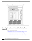
Connecting the Cables to the Cisco Unified MeetingPlace 8100 Series
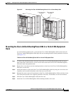
To Connect the T1 CAS Telephony Cables for a Cisco Unified MeetingPlace 8106
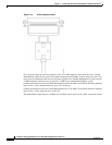
Step 1 Locate the T1 CAS telephony cables that shipped with the Cisco Unified MeetingPlace system. Each T1
CAS telephony cable has an RJ-48 connector on each end.
Step 2 Plug one end of the first T1 CAS telephony cable into the socket.
Step 3 Plug the other end of the first T1 CAS telephony cable into the T1 Smart Blade transition module in the
back of the Cisco Unified MeetingPlace 8106. Place the first T1 CAS telephony cable in the slot nearest
the right edge. (See
Table 2-1.)
Step 4 Repeat Step 2 and Step 3 until all the T1 CAS telephony cables are connected:
a. Place the second T1 CAS telephony cable in the second connector slot from the right.
b. Place the third T1 CAS telephony cable in the third connector slot from the right.
c. Place the fourth T1 CAS telephony cable in the fourth connector slot from the right.
Step 5 Install tie wraps and label the T1 CAS telephony cables as needed.
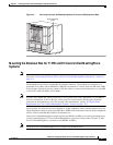
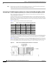
Connecting T1 CAS Telephony Cables for a Cisco Unified MeetingPlace 8112
Each T1 Smart Blade transition module has connectors for four trunk lines in the back of the Cisco
Unified MeetingPlace Audio Server.
Looking at the back of the Cisco Unified MeetingPlace Audio Server, the T1 Smart Blade transition
modules begin in slot 1 on the right and move to the left. The cables go from top to bottom in the right
most slot, then from top to bottom in the second most right slot, and so on to the left most slot, where
they continue going from top to bottom.
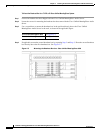
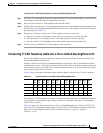
Table 2-2 shows the order in which the cables should be placed. Note that slots 7 to 10 are reserved.
The number of T1 CAS telephony cables that Cisco Systems ships with the Cisco Unified MeetingPlace
system depends on the number of ports being activated. Cisco Systems ships one T1 CAS telephony
cable for every 24 ports.
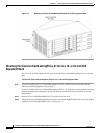
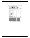
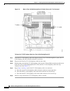
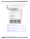
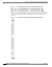
Figure 2-9 shows the cable connections for a Cisco Unified MeetingPlace 8112 with 1,152 T1 CAS
ports. Four T1 CAS telephony cables connect to each of the 12 T1 Smart Blade transition modules for a
total of 48 T1 CAS telephony cables. Each cable holds 24 ports for a total of 1,152 ports
(48
x 24 = 1,152).
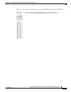
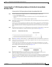
Ta b l e 2-2 Cable Locations in the Cisco Unified MeetingPlace 8112
Slot
16
Slot
15
Slot
14
Slot
13
Slot
12
Slot
11
Slot
6
Slot
5
Slot
4
Slot
3
Slot
2
Slot
1
Connector
45 41 37 33 29 25 21 17 13 9 5 1
Connector
46 42 38 34 30 26 22 18 14 10 6 2
Connector
47 43 39 35 31 27 23 19 15 11 7 3
Connector
48 44 40 36 32 28 24 20 16 12 8 4