


3-3
Cisco 811 and Cisco 813 Routers Hardware Installation Guide
78-10188-03
Chapter 3 Installation
Installing Your Router
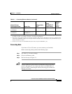
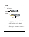
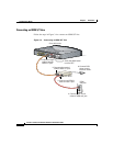
Connecting Hubs
If you have a Cisco 813 router, you can connect up to four hubs.
Before connecting a hub, perform the following steps:
Step 1 See Table 3-1 for router settings.
Step 2 Choose the Ethernet cable.
Step 3 Review the steps in Figure 3-1.
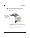
Caution Always connect the yellow cable or an Ethernet cable to the yellow
ports on the router. Do not connect the cable to an ISDN S/T or U
port or to a DSU. Connecting the cable to the wrong port or DSU can
damage your router.
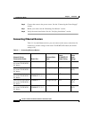
Server, PC, or
workstation
ETHERNET 1 Straight-through OUT —
Server, PC, or
workstation
Cisco 813 router:
ETHERNET 2, 3, 4
Straight-through —
3
—
1. Cisco provides a yellow straight-through cable. You must provide required crossover or additional straight-through cables.
For details on cables, see “Cabling” in Chapter 2, “Preparing for Installation.”
2. Hub vendors choose different names for the button controlling cable selections. This table uses the Cisco 1528 Micro Hub
10/100 with an MDI/MDI-X button as an example. Determine the button name and setting for your particular hub. See your
hub documentation for details.
3. On the Cisco 813 router, the TO HUB/TO PC button affects only the ETHERNET 1 port.
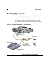
Table 3-1 Connecting Ethernet Devices (continued)
Network Device
Connected to Router Router Port
Ethernet Cable
Type
1
Router
TO HUB/TO PC
Button Setting
Network
Device
Button
Setting
2