


Chapter 3 Installation
Installing Your Router
3-4
Cisco 811 and Cisco 813 Routers Hardware Installation Guide
78-10188-03
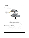
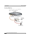
Figure 3-1 Connecting a Hub
To verify your hub connection, make sure that one of the following LEDs is on
after you have completed the router installation:
• ETHERNET 1 on the Cisco 811 router front panel.
• ETHERNET 1, 2, 3, or 4 on the Cisco 813 router front panel.
If the LED is not on, see Table 4-2 in Chapter 4, “Troubleshooting.”
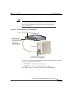
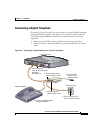
Connecting a Server, PC, or Workstation
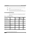
Before connecting a server, PC, or workstation, see Table 3-1 to determine how to
set the router TO HUB/TO PC button. Also, check your device to make sure it has
a 10- or 10/100-Mbps NIC.
To connect one of these devices, follow the steps in Figure 3-2.
ETHERNET
SPEED
1
5
2
6
3
7
4
8
LED
100BaseTX
SOLID
10BaseT BLINK
1X 2X
3X 4X
5X
6X
7X
MDI
MDI-X
8X
E
TH
E
RN
E
T 10 BA
S
E
T
T
O
H
U
B
TO
P
C
+5, -24
, -71
, VD
C
1
2
3
4
CO
N
S
O
LE
M
odel Cisco 813
ISD
N
S/T
P
H
O
N
E
12
IS
D
N
U
IS
D
N
U
NO
R
R
V
S
O
N
O
F
F
D
S
U
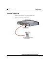
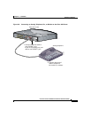
1. Set TO HUB/TO PC button.
4. If applicable, check setting
of hub equivalent of router
TO HUB/TO PC.
3. Connect other
end of cable
to hub.
2. Connect cable to:
• Yellow Ethernet port
on Cisco 811 router
• Any yellow
Ethernet port on
Cisco 813 router
Cisco 813 router
Cisco micro hub 10/100
33100