


1-8
Cisco ASR 901 Series Aggregation Services Router Hardware Installation Guide
OL-23778-01
Chapter 1 Introduction
Router Interface Numbering
Router Interface Numbering
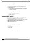
Each network interface on a Cisco ASR 901 router is identified by a slot number and a port number,
explained in this sequence:
• Logical slot numbers starts from 0 for all built-in interfaces. The numbering format is Interface
type Slot number/Interface number.
Interface (port) numbers begin at logical 0 for each interface
type.
• Logical interface numbering for T1/E1 ports on the TDM interface module runs from 0/0 through
0/15. Ports are numbered bottom to top, left to right.
• Logical interface numbering for the built-in ethernet ports runs from g0/0 through g0/3, the combo
ports run from g0/4 to g0/7 and the SFP ports run from g0/8 through g0/11. The GE ports are
numbered bottom to top, left to right.
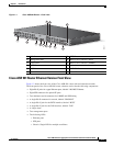
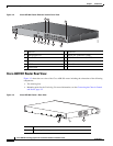
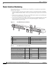
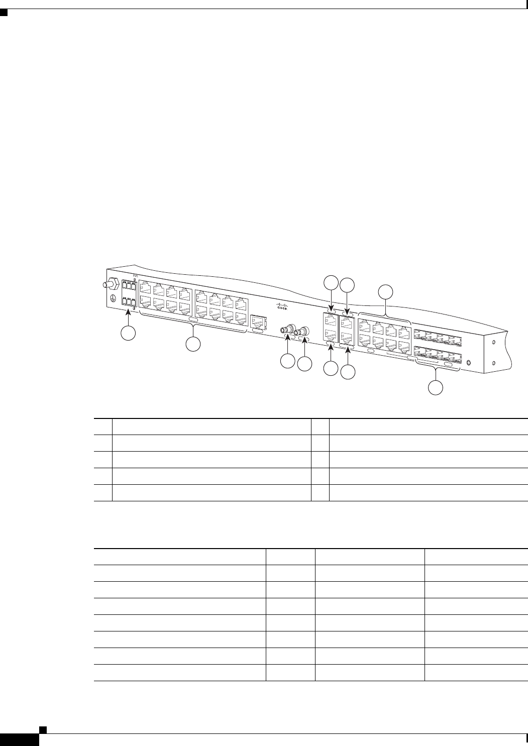
Figure 1-5 Cisco ASR 901 Router Port Numbers
282343
SYSTEM
CONSOLE
BITS
1 PPS
MGMNT
TOD
10 MHz
T1/E1
ALARM
B
A
+
-
+
-
24V - 60V
3A
COMBO
SFP
NG-MRW
GE
5
6
10
2
1
9
7
8
3
4
1 ToD Port 6 BITS Port
2 Management Port 7 MINI-Coax Connector (1PPS)
3 8 SFP Ports 8 MINI-Coax Connector (10MHZ)
4 8 GE Ports 9 16 T1/E1 Ports
5 Console Port 10 Power Connector
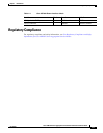
Table 1-4 Cisco ASR 901 Router Interface Labels
Interface Number Location Label
RJ45 jacks for copper ethernet ports 8 Onboard 100/1000 ETHERNET
SFP connector for optical GE ports 8 Onboard Fiber ETHERNET
RJ45 connector for console 1 Onboard CON/AUX
RJ45 jack for BITS interface 1 Onboard BITS
RJ45 jack for Time-of-Day interface 1 Onboard TOD
1PPS mini-coax timing connector 1 Onboard 1PPS
10Mhz mini-coax timing connector 1 Onboard 10MHZ