


A-5
Cisco ASR 901 Series Aggregation Services Router Hardware Installation Guide
OL-23778-01
Appendix A Troubleshooting
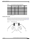
Reading the LEDs
T1/E1 Interface LEDs
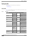
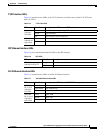
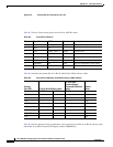
Table A-5 summarizes the LEDs on the T1/E1 interface (available only for A901-12C-FT-D and
A901-4C-FT-D).
LED Color/State Description (two LEDs for each T1/E1 port)
Active
(labele
d C,
left LED)
Green Carrier condition—operating without problem
Yellow Loop condition
Off Out of service or not configured
Alarm
(labele
d AL,
right LED)
Yellow Alarm condition
Off No alarm
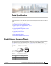
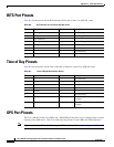
SFP Ethernet Interface LEDs
Table A-6 gives information about the LEDs on the SFP interface.
LED Color/State Description
SFP Link/Active
(labele
d LINK ACT)
Orange Link and active indicator
Off Link not enabled
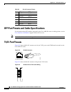
RJ-45 Ethernet Interface LEDs
Table A-7 summarizes the LEDs on the RJ-45 Ethernet interface.
LED Color/State Description (two LEDs for each 100/1000 Ethernet port)
100/1000
RJ-4
5 link
(labeled L,
left LED)
Solid Green Link with no activity
Flash Green Link with activity
Off No link detected
100/1000
R
J-45 speed
(labeled S,
right LED)
Green Speed 1000
Yellow Speed 100
Off Off
Table A-5 T1/E1 Port LEDs
Table A-6 SFP LEDs
Table A-7 100/1000 Ethernet Port LEDs