


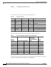
Console
Port (DTE)
1
RTS 1
2
8 5 CTS
DTR 2 7 6 DSR/DCD
TxD 3 6 3 RxD
GND/RI 4 5 7 GND
GND 5 4 7 GND/RI
RxD 6 3 2 TxD
DSR/DCD 7 2 20 DTR
CTS 8
2
1 4 RTS
B-5
Cisco ASR 901 Series Aggregation Services Router Hardware Installation Guide
OL-23778-01
Appendix B Cable Specifications
Console Port Signals and Pinouts
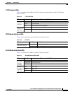
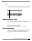
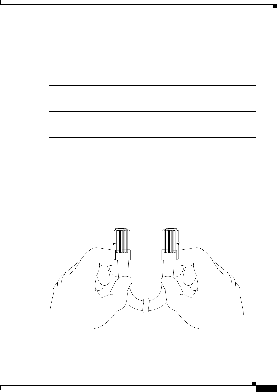
Identifying a Rollover Cable
To identify a rollover cable, compare the modular plugs at the two ends of the cable. When you hold the
plugs side by side, with the tab at the back, the wire connected to the pin on the outside of the left plug
should be the same color as the wire connected to the pin on the outside of the right plug (Figure B-5.)
If you purchased your cable from Cisco Systems, pin 1 is white on one connector, and pin 8 is white on
t
he other (a rollover cable connects pins 1 and 8, 2 and 7, 3 and 6, and 4 and 5).
Pin 1
Pin 8
H3824
Pin 1 and pin 8
should be the
same color
Figure B-5 Identifying a Rollover Cable
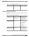
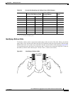
Table B-5 Console Port Signaling and Cabling Using a DB-25 Adapter
1. You can use the same cabling to connect a console to the auxiliary port.
RJ-45-to-RJ-45 Rollover Cable
RJ-45-to-DB-25
Terminal Adapter
Console
Device
Signal RJ-45 Pin RJ-45 Pin DB-25 Pin Signal
2. Pin 1 is connected internally to pin 8.