


C-2
Catalyst 3850 Switch Hardware Installation Guide
OL-26779-02
Appendix C Configuring the Switch with the CLI-Based Setup Program
Accessing the CLI
Accessing the CLI Through a Console Port
You can enter Cisco IOS commands and parameters through the CLI.
Note If you have stacked Catalyst 3850 switches, connect to the 10/100/1000 Ethernet management port or
console port of one of the stack switches. You can perform the initial configuration for the entire stack
on any switch in the stack.
Use one of these options to access the CLI:
• RJ-45 Console Port
• USB Console Port
RJ-45 Console Port
The RJ-45 console port is on the rear panel of the switch.
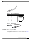
Step 1 Connect the RJ-45-to-DB-9 adapter cable to the 9-pin serial port on the PC. Connect the other end of the
cable to the switch console port.
Step 2 Start the terminal emulation program on the PC or the terminal. The program, frequently a PC
application, such as HyperTerminal or ProcommPlus, makes communication between the switch and
your PC or terminal possible.
Step 3 Configure the baud rate and character format of the PC or terminal to match the console port
characteristics:
• 9600 baud
• 8 data bits
• 1 stop bit
• No parity
• None (flow control)
Step 4 Connect power to the switch as described in Chapter 4, “Power Supply Installation.”
Step 5 The PC or terminal displays the bootloader sequence. Press Enter to display the setup prompt. Follow
the steps in the “Configuring the Setup Program” section on page C-5.
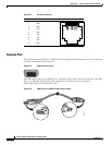
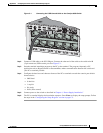
USB Console Port
The USB mini-Type B port is on the front panel of the switch.
Step 1 If you are connecting the switch USB console port (see Figure C-1) to a Windows-based PC for the first
time, install the USB driver, refer to “Installing the Cisco Microsoft Windows USB Device Driver”
section on page C-4.