


4-4
Catalyst 3850 Switch Hardware Installation Guide
OL-26779-02
Chapter 4 Power Supply Installation
Power Supply Module Overview
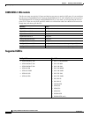
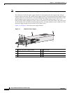
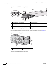
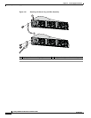
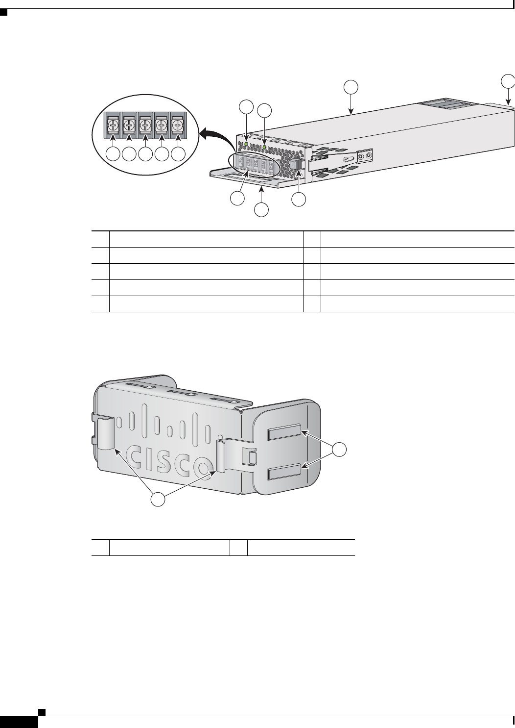
Figure 4-4 440-W DC Power Supply Module
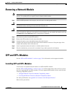
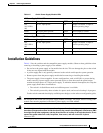
If no power supply is installed in a power supply slot, install a power supply slot cover (Figure 4-5).
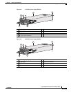
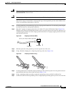
Figure 4-5 Power Supply Slot Cover
The power supply modules have two status LEDs.
1 440-W DC power supply module 6 Grounding terminal
2 DC OK LED 7 Release latch
3 PS OK LED 8 Extraction handle
4 Input power terminals (positive polarity) 9 Terminal block safety cover
5 Input power terminals (negative polarity) 10 Keying feature
DC OK
PWR-C1-440WDC
PS OK
334378
1
8
2
3
7
4
5 6 5 4
INPUT
-36 TO -72V
/12A
OUTPUT
44W MAX
/22A
9
10
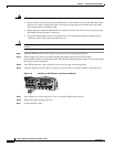
1 Release handles 2 Retainer clips
253564
2
1