


4-5
Catalyst 3850 Switch Hardware Installation Guide
OL-26779-02
Chapter 4 Power Supply Installation
Installation Guidelines
Installation Guidelines
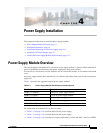
Table 4-1 lists the switches and the compatible power-supply modules. Observe these guidelines when
removing or installing a power supply or fan module:
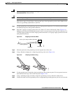
• Do not force the power supply or fan module into the slot. This can damage the pins on the switch
if they are not aligned with the module.
• A power supply that is only partially connected to the switch can disrupt the system operation.
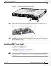
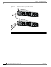
• Remove power from the power-supply module before removing or installing the module.
• The power supply is hot-swappable. In some configurations, such as full PoE+ or power sharing
mode, removing a power supply causes powered devices to shut down until the power budget
matches the input power of a single power supply. To minimize network interruption, hot swap the
power supply under these circumstances:
–
The switch is in StackPower mode and sufficient power is available.
–
The switch is powered by other switches in a power stack, and no active backup is in progress.
For the switch commands that display available power budget, see the software configuration guide.
Caution Do not operate the switch with one power-supply module slot empty. For proper chassis cooling, both
module slots must be populated, with either a power supply or a blank module.
Warning
Blank faceplates and cover panels serve three important functions: they prevent exposure to
hazardous voltages and currents inside the chassis; they contain electromagnetic interference (EMI)
that might disrupt other equipment; and they direct the flow of cooling air through the chassis. Do not
operate the system unless all cards, faceplates, front covers, and rear covers are in place.
Statement 1029
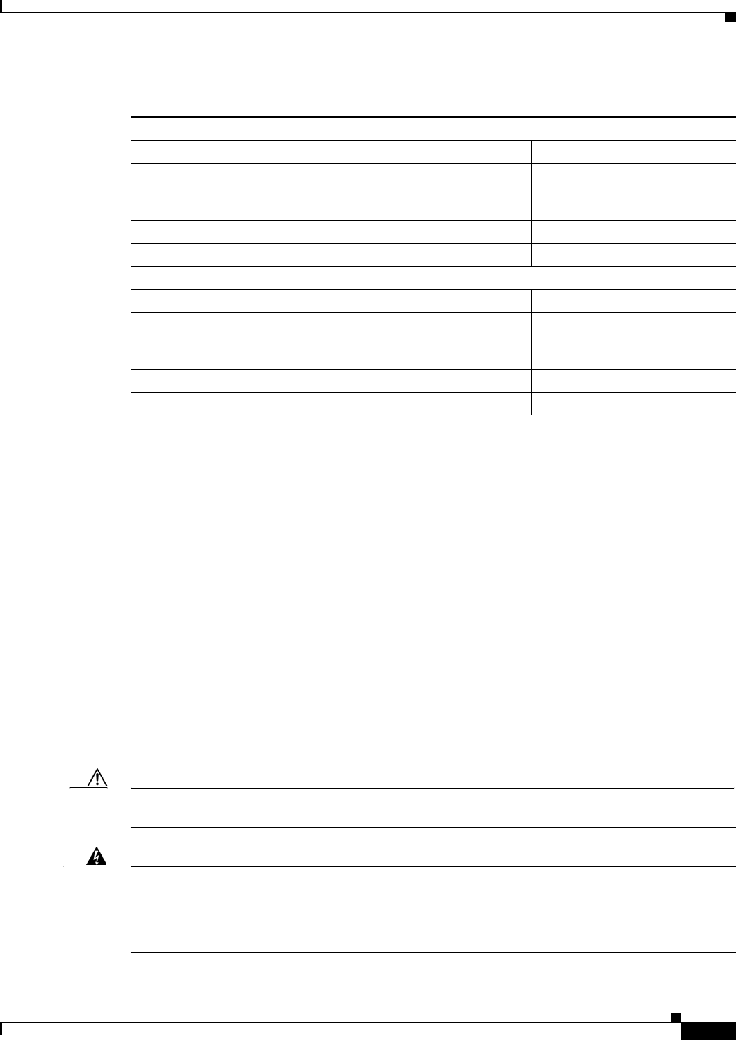
Table 4-2 Switch Power Supply Module LEDs
AC Power Supply Module LEDs
AC OK Description PS OK Description
Off
(AC LED is
off)
No AC input power. Off Output is disabled, or input is
outside operating range.
Green AC input power present. Green Power output to switch.
Red Output has failed.
DC Power Supply Module LEDs
DC OK Description PS OK Description
Off
(DC LED is
off)
No DC input power. Off Output is disabled, or input is
outside operating range.
Green DC input power present. Green Power output to switch.
Red Output has failed.