


A-21
Cisco 12404 Internet Router Installation and Configuration Guide
OL-11636-01
Appendix A Technical Specifications
Product Architecture
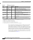
MBus Module Port Pin Assignments
Twenty general purpose pins and four analog input pins on the MBus module are
used for this design.
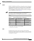
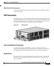
CSF Functionality
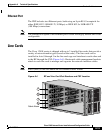
The CSF circuity provides synchronized speed interconnections for the line cards
and the RP (Figure A-5). The CSF circuitry consists of clock and scheduler, and
switch fabric functionality; is contained on one card, housed in the bottom slot in
the chassis. The CSF card has a switching capacity of 40 Gbps.
Figure A-5 CSF Card Slot
Clock and Scheduler Functionality
The CSF card generates and distributes system-wide clock and cell time
synchronization signaling. System clock generation is delivered to the system via
the backplane and local clock functions are derived from the system clock.
System Clock
The system clock synchronizes data transfers between line cards or between the
RP and a line card through the CSF. The system clock signal is sent to all line
cards and the RP.
66293
C
O
N
S
O
L
I
D
A
T
E
D
S
W
I
T
C
H
F
A
B
R
I
C
C
R
IT
IC
A
L
M
A
J
O
R
M
IN
O
R
MBUS
FAIL
ENABLE
A
L
A
R
M
F
A
B
R
IC
1
0
23
4
0C
48
/P
O
S
-SR
-S
C
T
X
R
X
A
C
T
I
V
E
C
A
R
R
I
E
R
R
X
P
K
T
C
L
A
S
S
1
L
A
S
E
R
P
R
O
D
U
C
T
L
A
S
E
R
P
R
O
D
U
K
T
D
E
R
K
L
A
S
S
E
1
P
R
O
D
U
I
T
L
A
S
E
R
D
E
C
L
A
S
S
E
1
P
R
O
D
U
C
T
O
L
A
S
E
R
D
E
C
LA
S
S
E
1
C
L
E
A
N
C
O
N
N
E
C
T
O
R
W
I
TH
AL
C
O
H
OL
W
I
PE
S
B
EF
O
RE
CO
NN
E
CT
IN
G
S
L
O
T
-
0
GIGABIT ROUTE PROCESSOR
S
L
O
T
-
1
C
O
L
L
L
IN
K
T
X
R
X
R
J
-4
5
M
II
R
E
S
E
T
AUX
E
J
E
C
T
C
O
N
S
O
L
E