


Appendix A Technical Specifications
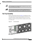
Fan Tray Assembly
A-26
Cisco 12404 Internet Router Installation and Configuration Guide
OL-11636-01
Warning
Allow sufficient air flow by maintaining 6 inches (15.24 cm) of clearance at both
the inlet and exhaust openings on the chassis because exhaust from other
equipment vented directly into the router air inlet may cause an over-heat
condition.
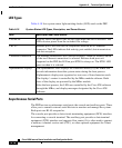
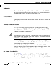
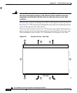
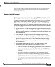
The fans draws room air in through an air filter on the opposite side of the chassis.
See Figure A-9. The fans draw air through the card cage and out through exhaust
vents on the opposite side of the chassis.
The front, back and sides of the Cisco 12404 router must remain unobstructed to
ensure adequate air flow and prevent overheating inside the RP and line card cage.
We recommend at least 6 inches (15.2 centimeters) of clearance on all sides.
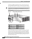
Figure A-9 Internal Air Flow—Top View
66281
Top view
1
6
2
3 3
55
4