


Appendix A Technical Specifications
Product Architecture
A-24
Cisco 12404 Internet Router Installation and Configuration Guide
OL-11636-01
A PFC allows the PEM to accept DC power source voltage from an AC power
source operating between 100 to 120 VAC, 15-Amp service in North America;
and a range of 185 to 264 VAC, 10-Amp service in an international environment.
Note Attach each DC PDU be connected to an independent power source for full
redundancy. Use an uninterruptable power source (UPS) to protect against power
failures at your site.
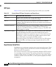
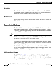
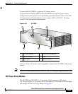
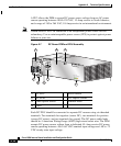
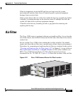
Figure A-7 DC Power PEM and PDU Assembly
Each DC PDU should be connected to separate DC sources using six threaded
terminals. Two terminals for negative (source DC), two terminals for positive
(source DC return), and two terminals for ground. The DC power cable leads
should be 4 American Wiring Gauge (AWG) high strand count wire. The PEM
accepts DC power source voltage from a dedicated 45–Amp service DC power
source operating between -48 to -60 VDC nominal input voltage and -40 to -72
VDC steady-state input voltage.
1 DC PDU 5 On/Off switch
2 DC PEM 6 PDU captive screws
3 PEM captive screws 7 Terminal block
4 LEDs
IN
P
U
T
–
48
/6
0V
3
5
A
66295
INPUT
OK
OUTPUT
FAIL
OUTPUT
OK
5
6
4
3
7
1 2 3