


Chapter 3 Installing the Router
Connecting to a DC Power Source
3-34
Cisco 12006 and Cisco 12406 Router Installation and Configuration Guide
OL-11497-03
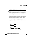
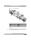
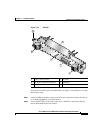
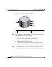
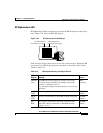
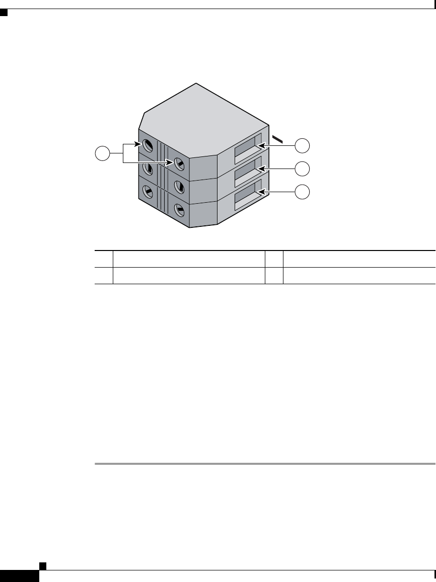
Figure 3-20 DC PDU Power Connector Block
Step 3 Connect the source DC power leads to the three terminal ports in the DC power
connector block (see
Figure 3-20) in this order:
• Ground lead first (bottom port on the connector block)
• Positive lead second (middle port on the connector block)
• Negative lead last (top port on the connector block)
a. Push the lead into the connector block port.
b. Use a flat-blade screwdriver to tighten the set screw and secure the lead.
c. Repeat Step 3a and Step 3b for the remaining leads and for the second PDU
connector block.
Step 4 Verify that the source DC circuit breaker servicing the DC PDU is switched on.
1 Negative terminal port 3 Ground terminal port
2 Positive terminal port 4 Terminal port connector screws
57993
POWER A
+
GND
1
4
2
3