


Jackscrew Installation Instructions (for EIP Ports) 3
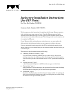
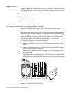
Figure 1 Ethernet Connector Locks, Slide-Type and Jackscrew-Type
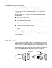
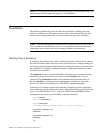
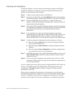
The EIP is the 2, 4, or 6-port high-speed Ethernet interface processor for the Cisco 7000
router. The EIP and other interface processors (IPs) slide into slots in the rear of the
router chassis (which is shown in Figure 2) and connect directly to the backplane. You
can replace the connector locks while the EIP is installed in the chassis, provided that
you first shut down the interface ports on which you will change connector locks.
Figure 2 shows a 6-port EIP installed in IP slot 1.
Figure 2 Cisco 7000 Chassis Rear View
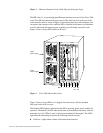
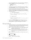
Figure 3 shows a 6-port EIP as it is shipped from the factory, with the standard
slide-type locks on all six ports.
The Enabled LED lights to indicate that the EIP is receiving power and is enabled for
operation. The bank of 18 LEDs indicate the state of the individual interfaces, with one
horizontal row of 3 LEDs for each of the 6 ports (numbered 0 through 5). The LEDs
light when the indicated port detects the following network activity:
■ Collision—Lights when a frame collision has been detected.
H1725
Slot 0
1
2
34SP
slot
RP
slot
Upper
power supply
Lower
power supply
I
O
DC FAIL
AC POWER
I
O
DC FAIL
AC POWER