


8Jackscrew Installation Instructions (for EIP Ports)
Step 4: Repeat steps 2 and 3 for all addition ports that require jackscrews.
Step 5: Place the removed brackets and slotted screws aside; you can discard them
after the jackscrews are installed, and the installation is complete.
Installing the Screw-Type Lock
Use the hardware provided in the replacement kit to reinstall the connector. Do not use
any of the hardware you removed from the slide-type lock bracket.
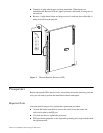
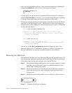
Step 1: Ensure that the slide-type lock bracket, shown in Figure 5, has been removed
from the connector port.
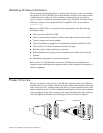
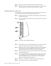
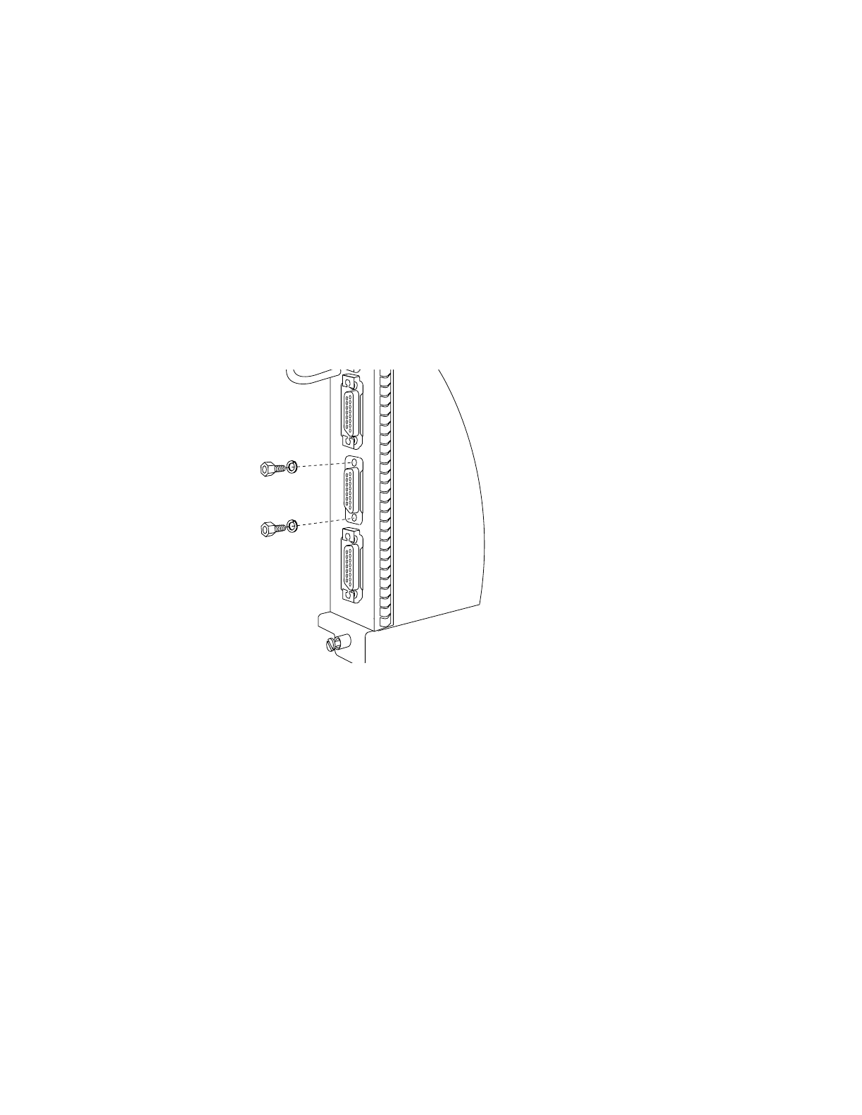
Step 2: Insert a lock washer onto the shaft of a jackscrew and push it up to the head
of the jackscrew.
Figure 6 Jackscrew and Lock Washer Installation
Step 3: Insert the jackscrew into one of the threaded holes on the connector. Turn the
jackscrew clockwise about two full turns to thread it into the hole.
Step 4: Repeat steps 2 and 3 for the second jackscrew and lock washer, placing the
second jackscrew in the other threaded hole on the connector. Turn the
jackscrew clockwise about two full turns to thread it into the hole.
Step 5: Observe both jackscrews edge-on and turn them another half turn to ensure
they are threaded properly.
Step 6: Use the 3/16-inch nut driver to tighten the jackscrews in the connector. Do
not overtighten the screws; the lock washer will secure the jackscrews in
place, and the thumbscrews on the cable connector, when inserted and
tightened, will further tighten the jackscrews.
Step 7: Repeat steps 1 through 6 for all addition ports that require jackscrews.
Step 8: Proceed to the next section to check the installation.
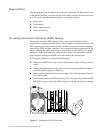
EIP
H1458a