


12 Cisco 7000 and Cisco 7507 LED Board Replacement Instructions
Removing and Replacing the LED Board
Removing and Replacing the LED Board
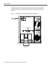
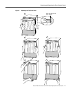
The LED board slides horizontally into two mounting brackets near the top of the chassis interior
and connects directly to the backplane. You must turn all system power off and remove the top and
bottom front chassis panels to access the chassis interior.
Warning Read the installation instructions before you connect the system to its power source. (For
translation of this safety warning, refer to the section “Installation Warning” on page 19.)
Warning This unit might have more than one power cord. To reduce the risk of electric shock,
disconnect the two power supply cords before servicing the unit. (For translation of this safety
warning, refer to the section “Electric Shock Warning” on page 17.)
Note The following warning is for units with DC-input power supplies.
Warning Before performing any of the following procedures, ensure that power is removed from
the DC circuit. To ensure that all power is OFF, locate the circuit breaker on the panel board that
services the DC circuit, switch the circuit breaker to the OFF position, and tape the switch handle of
the circuit breaker in the OFF position. (For translation of this safety warning, refer to the section
“DC Power Disconnection Warning” on page 17.)
Removing the LED Board
To remove the existing LED board, perform the following steps:
Step 1 Ensure that all system power is turned OFF and that power cords are disconnected from the
power supplies or the power source.
Step 2 Follow the steps in the section the section “Removing the Panels” on page 8 to remove the
top and bottom front chassis panels.
Step 3 If you have not already done so, slip on an ESD-prevention grounding strap. (A disposable
wrist strap is included with all spare boards.) Connect the equipment end of the strap to an
unpainted surface inside the chassis, such as the metal frame that is exposed when the front
panels are removed.
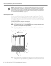
Step 4 Locate the LED board (see Figure 4), which is mounted on a horizontal plane in two plastic
brackets near the top of the chassis.
Step 5 Two steel pins near the front of the brackets hold the board in place. (See Figure 3.) On each
pin, place your thumb on the top of the pin and your forefinger underneath the bracket to
support it, and press the pins down and out of the guide holes in the board.
Caution Handle the LED board by the edges only to avoid damage from ESD.
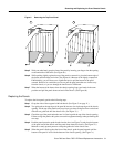
Step 6 Grasp the edges of the board and place a finger on the top of the LED board spring to
depress it.