


8 Cisco 7000 and Cisco 7507 LED Board Replacement Instructions
Removing and Replacing the Front Chassis Panels
Warning Before performing any of the following procedures, ensure that power is removed from
the DC circuit. To ensure that all power is OFF, locate the circuit breaker on the panel board that
services the DC circuit, switch the circuit breaker to the OFF position, and tape the switch handle of
the circuit breaker in the OFF position. (For translation of this safety warning, refer to the section
“DC Power Disconnection Warning” on page 17.)
Removing the Panels
You must remove the bottom front panel before you can remove the top front panel. The plastic
bottom front panel is attached to the chassis with ball studs. The top front panel is attached to the
chassis with two captive screws. The EMI shielding around the outer edge of the top front panel acts
as a spring, and compresses when you push the panel into the chassis to keep the panel fitted tightly
into the chassis opening.
To remove the front panels, perform the following steps:
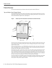
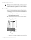
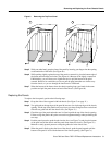
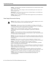
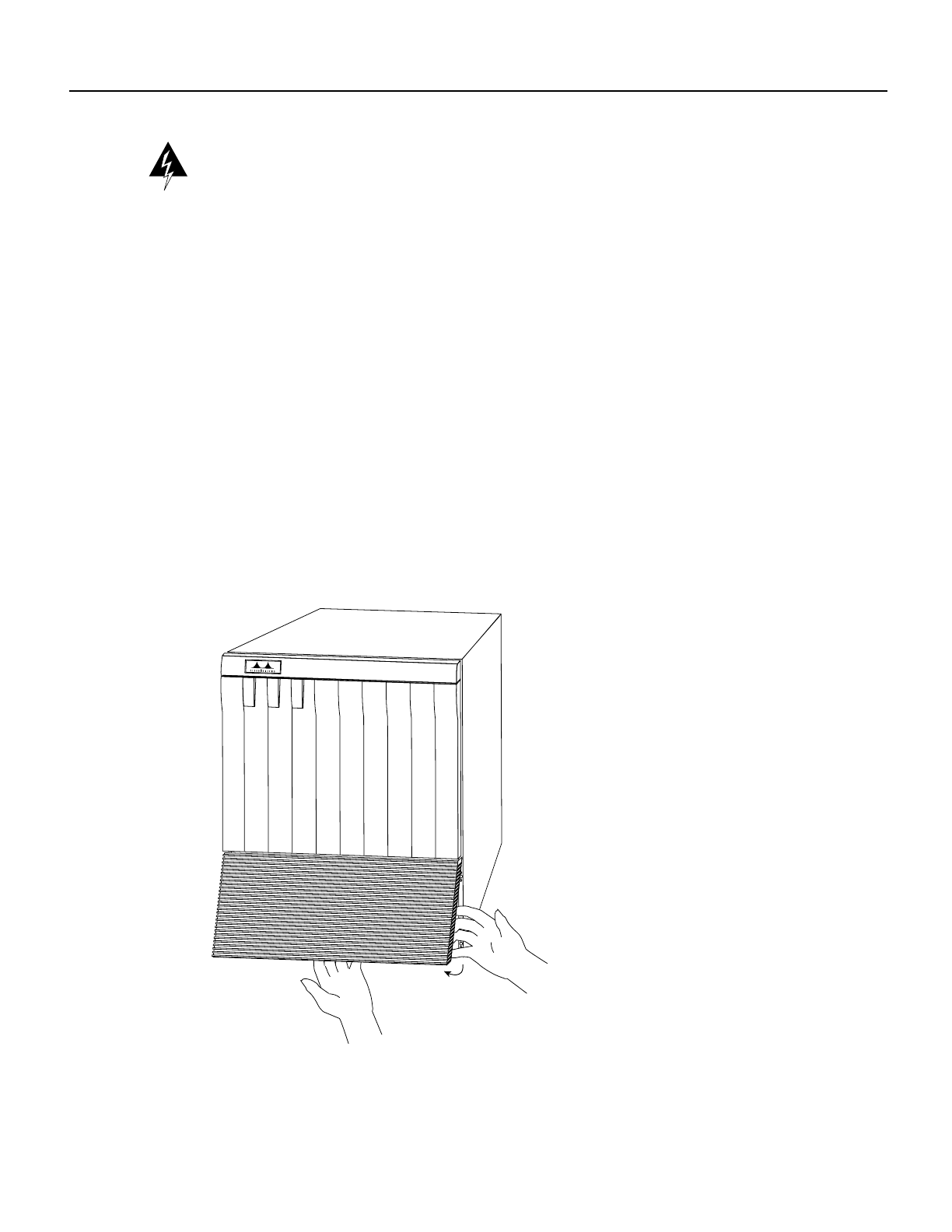
Step 1 Grasp the bottom edge of the bottom chassis panel.
Step 2 Pull the bottom of the panel out about one inch, then place your fingers behind the sides of
the panel and pull it off the chassis. (See Figure 5.)
Step 3 On the top front panel, use a screwdriver to loosen the two captive screws at the bottom
edge of the panel frame.
Figure 5 Removing the Bottom Front Panel
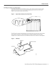
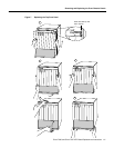
Step 4
Place one hand against the top front center of the panel to brace it. (See Figure 6a.) The top
of the panel acts as a pivot point when you pull the bottom out and away from the chassis.
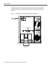
UPPER
POWER
LOWER
POWER
NORMAL
Cisco 7000
H1335a