


Cisco 7000 and Cisco 7507 LED Board Replacement Instructions 3
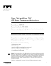
Product Overview
LED Board Location and Description
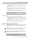
The LED board contains the three LEDs that report system software (normal) and power supply
(upper power and lower power) status through semiopaque panels on the front of the chassis.
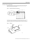
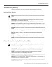
Figure 2 shows the three system status indicators.
Figure 2 System Status Indicators (Front-Panel LEDs)
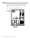
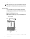
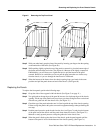
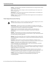
The LED board is mounted to the backplane on a horizontal plane near the top of the chassis interior
(shown edge-on in Figure 4). The board slides into two brackets mounted to the front of the
backplane, and a connector on the rear of the LED board mates with a connector on the backplane.
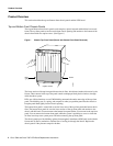
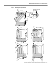
Figure 3 LED Board
UPPER
POWER
LOWER
POWER
NORMAL
Cisco 7000
UPPER
POWER
LOWER
POWER
NORMAL
H1407a
H1387a
LED board
brackets
Board locking
pin
LED board
spring
Backplane connector
LEDs
LED board