


14 Cisco 7000 and Cisco 7507 LED Board Replacement Instructions
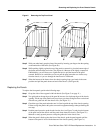
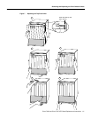
Removing and Replacing the LED Board
Installation Checkout
Perform the following steps to verify that the new LED board functions correctly.
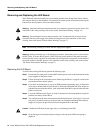
Note The following warning is for units with DC-input power supplies.
Warning After wiring the DC power supply, remove the tape from the circuit breaker switch handle
and reinstate power by moving the handle of the circuit breaker to the ON position. (For translation
of this safety warning, refer to the section “DC Power Connection Warning” on page 18.)
Step 1 Turn all power supplies back ON and observe the three system status indicators on the front
panel.
Step 2 When you turn each power supply ON, the corresponding upper power and lower power
LEDs on the front panel should go on for each bay in which a power supply is installed and
turned ON. If any do not go on, do the following:
• Check the AC power LED on the power supply. If it is on, suspect that the front panel
LED has failed and proceed with the installation checkout to determine if the other
LEDs go on.
• If the AC power LED is not on, or if the DC fail LED is on, ensure that the power supply
is fully inserted in the power supply bay and that the captive installation screw on the
top of the supply is tightened. The switch will not turn completely to the ON (|) position
unless the supply is installed correctly.
• Ensure that the power cord is fully seated in the power supply port and that the retention
clip is snapped up around the plug.
• Check the cable connection at the power source and ensure that it is connected properly.
• If the AC Power on the power supply still fails to go on, suspect a power supply failure.
If a second (redundant) power supply is available and functioning properly, proceed
with the installation checkout.
Step 3 After the system boots successfully, verify that the front panel normal LED goes on. If it
does not go on, do the following:
• Check the normal LED on the RP (in the Cisco 7000) or the RSP2 (in the Cisco 7507).
If it is on, the system software is functioning properly. Turn all power supplies OFF and
reseat the LED board by following steps 2 through 6 in the section “Installing a New
LED Board” on page 13.
• If the (RP or RSP2) normal LED fails to go on, the system software has failed to boot
properly. Toggle the power supplies OFF then ON again and observe the behavior of the
LEDs on the RP or RSP2, so that you can report it to a service representative if you need
to call for technical assistance.
This completes the installation checkout.