


Send document comments to nexus3k-docfeedback@cisco.com
D-3
Cisco Nexus 3000 Series Hardware Installation Guide
OL-25338-04
Appendix D LED Descriptions
Chassis and Module LEDs for the Cisco Nexus 3000 Series Switches
For a description of the status indicated by the two power supply LEDs, see the “Power Supply Status”
section on page D-3.
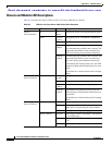
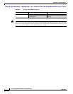
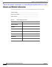
Power Supply Status
This section describes the power supply LED indicators for the Cisco Nexus 3000 Series switches.
Table D-2 describes the status indicated by the two LEDs on each power supply.
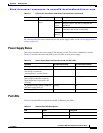
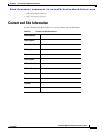
Port LEDs
Table D-3 lists the LED descriptions for the RJ-45 Ethernet port LEDs.
Port LED Indicates LED
status
Off The port is not active or the link is not connected.
Solid on
(green)
The port is active. The link is connected and
operational.
Solid on
(amber)
The module or port is disabled through the CLI
command or the module is initializing.
Blinking
(amber)
The port is faulty and has been disabled.
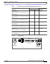
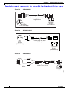
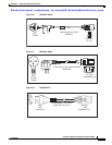
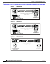
Table D-1 LEDs for the Cisco Nexus 3000 Series Fabric Extenders (continued)
Component LED Status Description
Ta b l e D-2 Power Supply Status Indicated by the OK and FAIL LEDs
Condition OK LED Status (Green) FAIL LED Status (Amber)
No AC power to the power supplies Off Off
Power supply failure (includes
overvoltage, overcurrent,
overtemperature, and fan failure)
Off On
Power supply warning events where the
power supply continues to operate
(high temperature, high power, and
slow fan)
Off 1 blinking
AC present/voltage standby (VSB) on,
and power supply unit off
blinking Off
Power supply On and OK On Off
Ta b l e D-3 Ethernet Port LED Descriptions
LED Status Description
Left Off No link
Solid green Physical link