


Send document comments to nexus3k-docfeedback@cisco.com
2-7
Cisco Nexus 3000 Series Hardware Installation Guide
OL-25338-04
Chapter 2 Installing the Cisco Nexus 3000 Series Switches
Installing the Switch
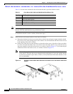
c. Attach the front-mount bracket using four M4 screws. Tighten the screws to 12 in-lb (1.36 N·m).
d. Repeat Steps 1a, 1b, and 1c with the other front rack-mount bracket on the other side of the switch.
Step 2 Install the rear rack-mount guides on the chassis as follows:
a. Align the two screw holes on a rear rack-mount bracket to the middle two screw holes in the
remaining six holes on the side of the chassis. If you are aligning the guide to holes that are near
the port connections end of the chassis, see Callout 3 in
Figure 2-1. Otherwise, see Callout 7 in
Figure 2-1.
b. Attach the guide to the chassis using two M4 screws. Tighten the screws to 12 in-lb (1.36 N·m).
See Callout 4 or 8 in
Figure 2-2.
c. Repeat Steps 2a and 2b with the other rear rack-mount bracket on the other side of the switch.
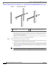
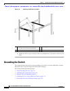
Step 3 Install the slider rails on the rack or cabinet as follows:
a. Determine which two posts of the rack or cabinet you should use for the slider rails. Of the four
vertical posts in the rack or cabinet, two will be used for the front mount brackets attached to
the easiest accessed end of the chassis, and the other two posts will have the slider rails.
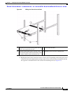
a. Position a slider rail at the desired level on the back side of the rack and use two 12-24 screws
or two 10-32 screws, depending on the rack thread type, to attach the rails to the rack. See
Figure 2-3.
Note For racks with square holes, you might need to position a 12-24 cage nut behind each mounting
hole in a slider rail before using a 12-24 screw.
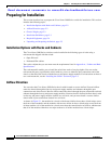
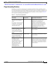
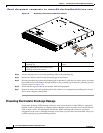
1 Front rack-mount bracket aligned to the
module end of the chassis
5 Front rack-mount bracket aligned to the port
connections end of the chassis
2 Four M4 screws used to attach the bracket to
the chassis
6 Four M4 screws used to attach the bracket to
the chassis
3 Rear rack-mount guide aligned to the port
connection end of the chassis
7 Rear rack-mount guide aligned to the module
end of the chassis
4 Two M4 screws used to attach the bracket to
the chassis
8 Two M4 screws used to attach the bracket to
the chassis