


96
Installing and Upgrading Internal Components in Cisco 3800 Series Routers
OL-5975-04
PVDM Installation and Removal
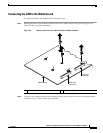
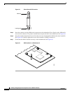
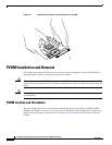
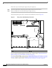
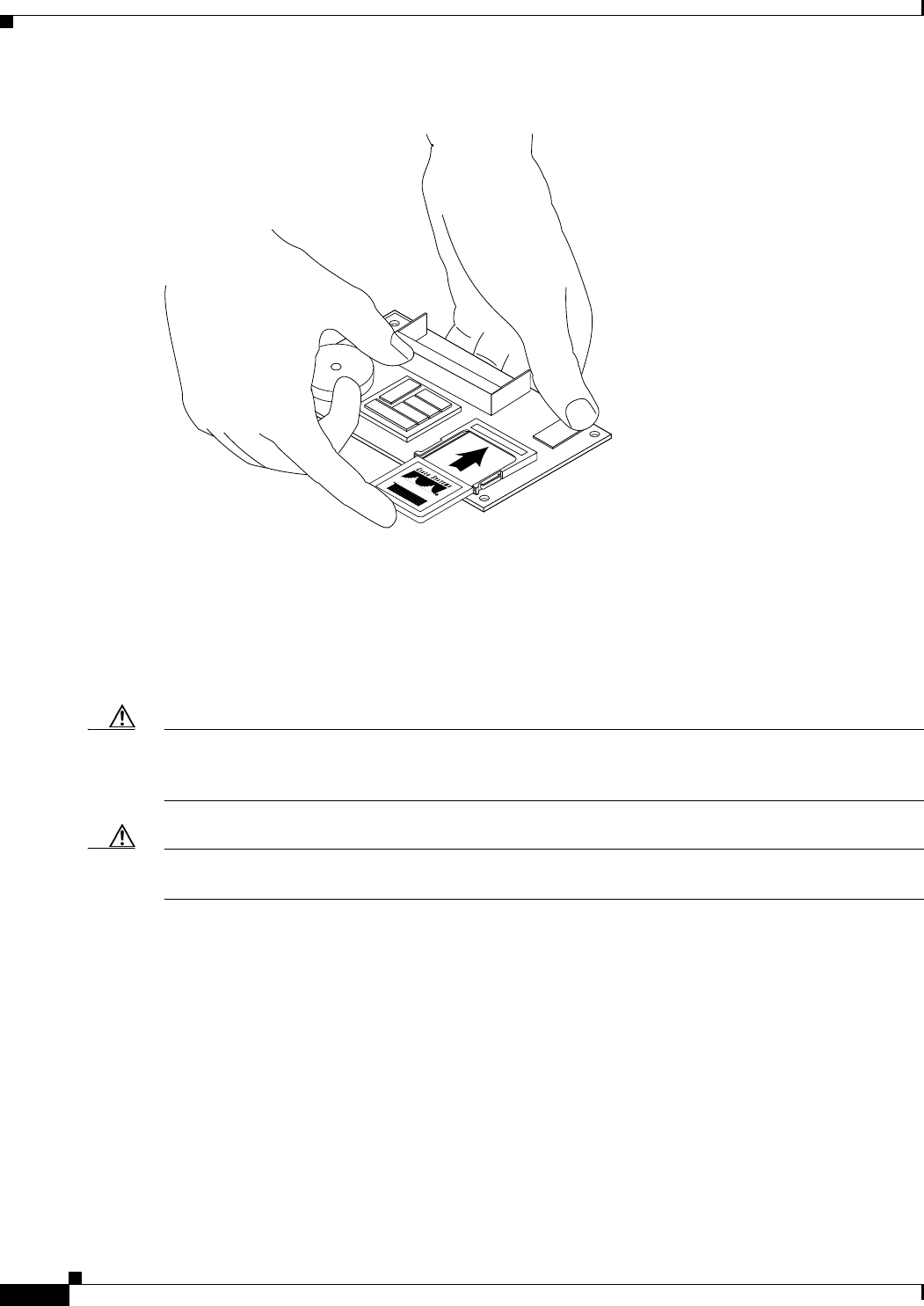
Figure 63 CompactFlash Memory Card Installation on the AIM
PVDM Installation and Removal
Cisco 3800 series routers hold up to four Cisco packet voice data modules, version II (PVDM-II), to
support enhanced versions of digital signal processors (DSPs).
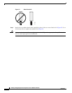
Caution When you remove or install PVDMs, always wear an ESD-preventive wrist strap, and ensure that it
makes good contact with your skin. Connect the equipment end of the wrist strap to the metal part of the
router.
Caution Handle PVDMs by the edges only. PVDMs are ESD-sensitive components and can be damaged
by mishandling.
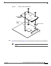
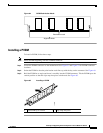
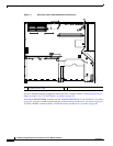
PVDM Location and Orientation
The four PVDM connectors are located on the motherboard and are identified as PVDM0, PVDM1,
PVDM2, and PVDM3. See Figure 51 and Figure 52 for PVDM locations. PVDMs have a polarization
notch on the mating edge to prevent incorrect insertion. Figure 64 shows the polarization notch on a
PVDM.
120376