


Chapter 4 Installation and Maintenance
Installing the SCE 1000 Platform
Cisco SCE 1000 2xGBE Installation and Configuration Guide
4-10 OL-7821-04
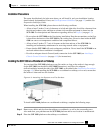
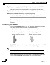
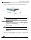
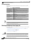
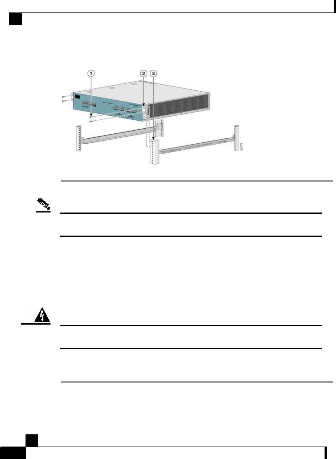
Step 4 While keeping the brackets flush against the posts or mounting strips, align the holes in the
brackets with the holes on the rack or mounting strip.
Figure 4-9: Securing the SCE 1000 to the Rack
Step 5 For each bracket, insert and tighten two appropriate screws to the rack.
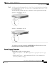
Note
Since the brackets support the weight of the entire SCE 1000 chassis, be sure to use all four screws to
fasten the two rack-mount brackets to the rack posts.
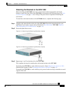
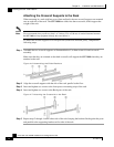
Attaching a Chassis Ground Connection
Before you connect the power or turn on the power to the SCE 1000 platform, it is required that
you provide an adequate chassis Ground (protective earth) connection for the SCE 1000 chassis.
A Grounding kit is provided with each SCE 1000.
Use the Grounding kit to properly ground the SCE 1000 chassis (see SCE 1000 Component List
(on page 2-5) for details).
Warning
When installing the unit, the chassis ground connection must always be made first and disconnected
last.
To connect the grounding cable to the chassis grounding connector on the SCE 1000, complete
the following steps:
Step 1 From the enclosed Grounding kit, remove the necessary materials — the grounding cable (green
and yellow colored cable) and pairs of hex nuts and spring washers.
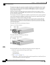
Step 2 On the Rear panel of the SCE 1000, locate the chassis grounding connector (refer to the
appropriate figure for an AC- or DC-powered SCE 1000 below).