


Chapter 6 Cabling the Line Ports and Completing the Installation
Connecting the line ports to the network
Cisco SCE 1000 2xGBE Installation and Configuration Guide
6-6 OL-7821-04
Fiber Specifications
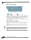
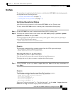
The following table presents the fiber specifications. The SCE 1000 may be ordered with either
Multimode or Single Mode transceivers The transceiver type is indicated on the front panel under
the ports. Note that both transceivers on any individual SCE 1000 are the same, either 850nm
Multimode OR 1310nm Single Mode.
Table 6-1 Fiber Specifications
SCE Model Transceiver Transmit Power Receive Power Typical (Max.) Distance
SCE 1000 2xGBE
MM
850nm Multimode –9.5 to –4 dBm –17 to 0 dBm
• 750m for 50µm Core
Diameter MMF
• 400m for 62.5µm Core
Diameter MMF
SCE 1000 2xGBE
SM
1310nm FRP laser
Single Mode
–9.5 to –3 dBm –20 to 3 dBm 10 km for 9.0µm Core
Diameter SMF
Cabling the GBE Port
Warning
Class 1 laser. Avoid exposure to radiation and do not stare into open aperture.
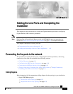
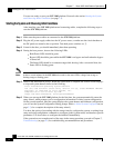
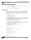
To cable the SCE 1000 GBE line port, complete the following steps:
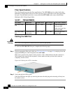
Step 1 Take the appropriate fiber optic cable (see Fiber Specifications (on page 6-6)) and plug it into the
appropriate GBE port on the front panel of the SCE 1000.
Make sure to push on the connector until you hear a click, which indicates that the connector is
fully inserted and secured in the receptacle. Always make sure that you insert the connector
completely into the socket.
Figure 6-3: Cabling the <ETH> Interface
Step 2 Verify that the link LED is green.
If the link LED does not light, try removing the network cable plug and reinserting it firmly into
the module socket.