


1-19
PA-2FE-TX and PA-2FE-FX Two-Port Fast Ethernet Port Adapter Installation and Configuration
OL-3474-07
Chapter 1 Overview
Identifying Interface Addresses
Cisco 7500 Series Routers VIP Interface Addresses
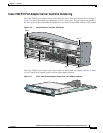
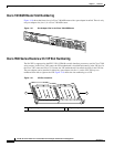
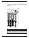
In Cisco 7500 series routers, port adapters are installed on a versatile interface processor (VIP), which
installs in interface processor slots 0 through 12 (depending on the number of slots in the router). The
port adapter can be installed in either bay (port adapter slot 0 or 1) on the VIP. See Figure 1-19,
Figure 1-20, Figure 1-21, and Figure 1-22.
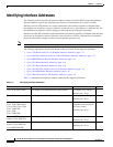
The interface address for the VIP is composed of a three-part number in the format
interface-processor-slot-number/port-adapter-slot-number/interface-port-number. See Table 1-4.
The first number identifies the slot in which the VIP is installed (slot 0 through 12, depending on the
number of slots in the router).
The second number identifies the bay (port adapter slot) on the VIP in which the port adapter is installed
(0 or 1). The bays are numbered from left to right on the VIP.
The third number identifies the physical port number (interface port number) on the port adapter. The
port numbers always begin at 0 and are numbered from left to right. The PA-2FE is a dual-port port
adapter, therefore the port can be 0 or 1.
For example, if a dual-port PA-2FE is installed in a VIP in interface processor slot 3, port adapter slot 1,
the interface addresses would be 3/1/0 and 3/1/1.
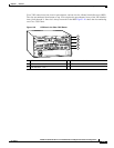
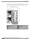
Note Although the processor slots in the seven-slot Cisco 7507 and the thirteen-slot Cisco 7513 chassis are
vertically oriented and those in the five-slot Cisco 7505 are horizontally oriented, all Cisco 7500 series
routers use the same method for slot and port numbering.