


10
Installation Notes for Catalyst 3750-E, Catalyst 3560-E Switches and RPS 2300 Power Supply Modules
78-17570-01
Power Supply Module Installation
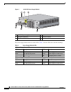
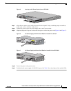
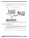
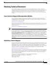
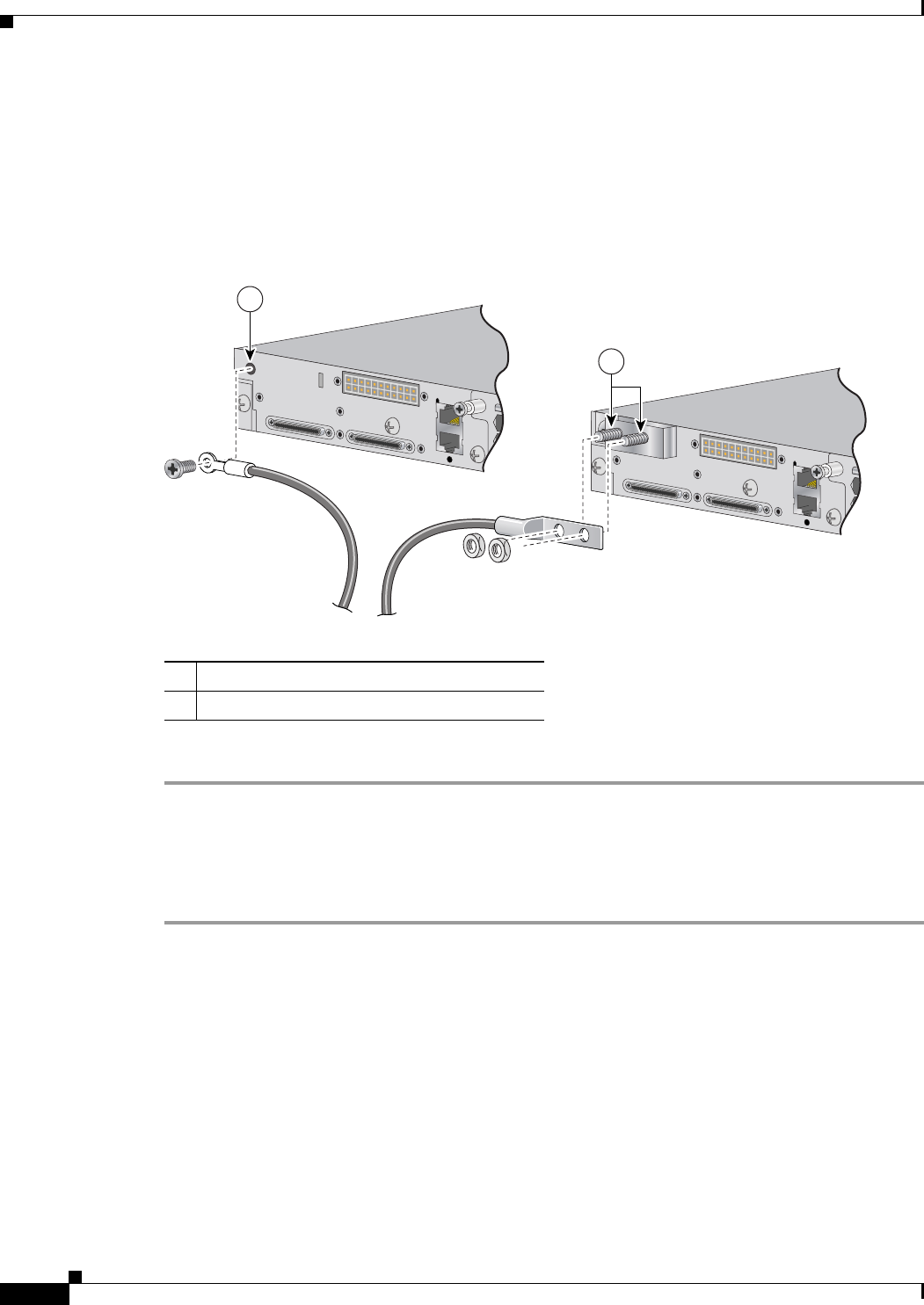
Step 5 Use the ground screw to attach the single-ground lug and wire assembly or the dual-ground adaptor to
the switch rear panel. Using a ratcheting torque screwdriver, torque the ground-lug screw to 60 lbf-in.
(960 ozf-in.) (Figure 10).
Step 6 For a dual-ground adaptor, attach the dual-hole lug and wire assembly to the adaptor with the supplied
nuts (Figure 10).
Figure 10 Attaching the Ground Lug and Wire Assembly
Step 7
Connect the other end of the grounding wire to an appropriate grounding point at your site or to the rack.
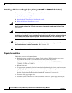
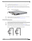
Installing the DC Power Supply in the Switch
To remove and install a DC-powered power supply module, follow these steps:
Step 1 Turn off power at the DC circuits. To ensure that power is removed from the DC circuits, locate the
circuit breakers for the DC circuits, switch the circuit breakers to the OFF position, and tape the
circuit-breaker switches in the OFF position.
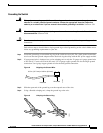
Step 2 Use a number-2 Phillips screwdriver to remove the plastic safety cover from the power supply terminal
blocks.
Step 3 Use a number-1 Phillips screwdriver to remove the DC-input power wires from the power terminals.
1 Single-ground screw and lug ring
2 Dual-ground adaptor and dual-hole lug
FR
F
157547
1
2