


11
Installation Notes for Catalyst 3750-E, Catalyst 3560-E Switches and RPS 2300 Power Supply Modules
78-17570-01
Power Supply Module Installation
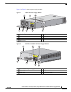
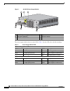
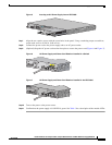
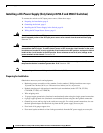
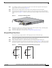
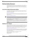
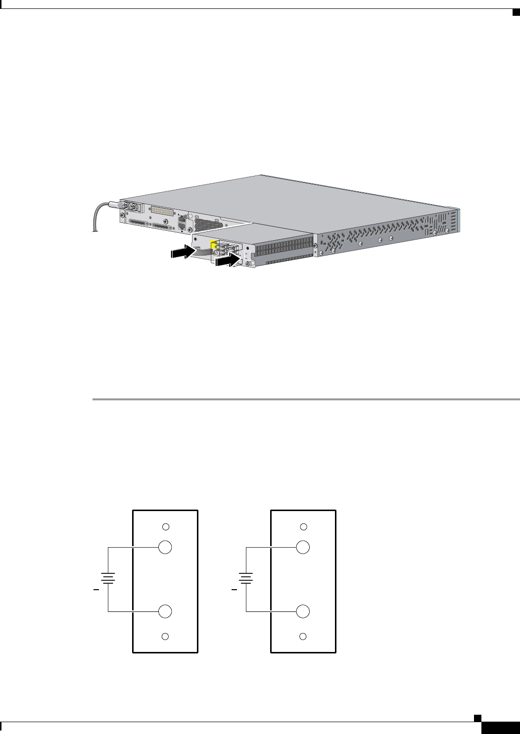
Step 4 Use a Phillips screwdriver to loosen the two captive screws at the lower edge that secure the power
supply module to the switch chassis (Figure 11).
Step 5 Remove the power supply module from the power slot by pulling on the extraction handle.
Step 6 Insert the new power supply into the power supply slot, and gently apply pressure while pushing the
module into the slot (Figure 11). When correctly inserted, the power supply is flush with the switch rear
panel.
Figure 11 Inserting the a DC-Power Supply
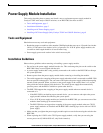
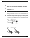
Step 7
Align the two captive screws with the screw holes in the switch rear panel. Using a ratcheting torque
screwdriver, torque each screw to 10 lbf-in. (160 ozf-in.).
Step 8 Connect the input power as described in the “Wiring the DC-Input Power Source”.
Wiring the DC-Input Power Source
To wire the DC-power supply module to a DC-input power source, follow these steps.
Step 1 Using a wire-stripping tool, strip each of the four wires coming from the DC-input power source to the
appropriate length for either the round eyelet or the fork-type terminals.
Step 2 Using a Panduit crimping tool, crimp the terminals to the 16-gauge DC-power input wires.
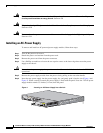
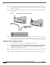
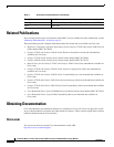
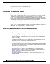
Step 3 Connect the DC-input power terminals to the terminal blocks as shown in Figure 12. Make sure to match
the polarity (negative to negative, positive to positive) when connecting the wires to the terminal blocks.
Figure 12 Source A Isolated From Source B with No Common Ground
158123
FRU CC 265W
D
C
IN
PS
O
K
A
+
A
+
IN
P
U
T
-3
6 to
-7
2V
/1
2
A
O
U
T
P
U
T
2
65
W
M
A
X
/2
2
A
B+
157718
B-
+
A+
A-
+