


7
Installation Notes for Catalyst 3750-E, Catalyst 3560-E Switches and RPS 2300 Power Supply Modules
78-17570-01
Power Supply Module Installation
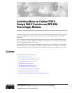
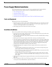
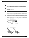
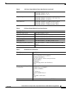
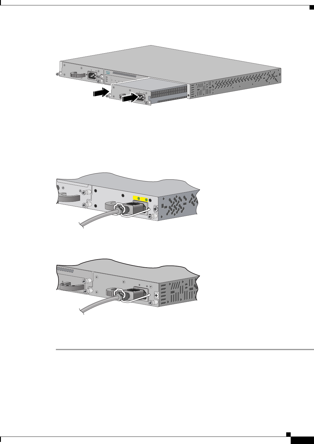
Figure 5 Inserting an AC-Power Supply into an RPS 2300
Step 7 Align the two captive screws with the screw holes in the panel. Using a ratcheting torque screwdriver,
torque each screw to 10 lbf-in. (160 ozf-in.).
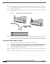
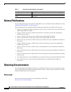
Step 8 Connect the power cord to the power supply and to an AC-power outlet.
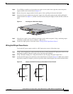
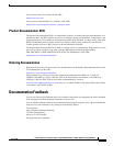
Step 9 (Optional) Snap the AC power cord retainer into place to secure the power cord (Figure 6 and Figure 7).
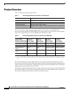
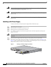
Figure 6 AC-Power Supply and Power Cord Retainer Installed in a Switch
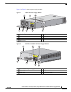
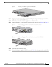
Figure 7 AC-Power Supply and Power Cord Retainer Installed in the RPS 2300
Step 10
Turn on the power at the power source.
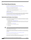
Step 11 Confirm that the power supply AC OK LED is green. See Table 3 for a description of the module LEDs.
Cisco RPS 2450
STDBY /
ACTIVE
1
TEMP
FAN
2
3
4
DC OUTPUT
SELECT
STDBY/
ACTIVE
5
6
AC OK
DC OK
1
0
0-
24
0
V
1
0
-5
A
5
0
-6
0
H
Z
A
C
O
K
D
C
O
K
100-240 V
1
0-5 A
50-6
0 H
Z
1
0
0
-2
4
0
V
10
-
5
A
5
0-
6
0
H
Z
100-240 V
10
-5 A
50-6
0 HZ
157544
157706
AC OK
PS OK
100-240 V
10-5 A
50-60 HZ
STDBY/
ACTIVE
5
6
Redundant Power System 2300
AC OK DC OK
100-240 V
10-5 A
50-60 HZ
200107