


1-31
Cisco SFS 7012 InfiniBand Server Switch Hardware Users Guide
OL-8787-05
• Hot swap one module at a time, allowing the chassis to completely update it before hot-swapping
the next module. The module update is complete when it becomes visible within the Chassis Viewer
GUI. Listed below are the approximate times to fully update each module type:
–
Spines modules: up to 4 minutes
–
Leaf modules: up to 2 minutes
• When a management spine is hot swapped, the rest of the chassis will continue to move packets
without interruption.
• There is no need to reboot the chassis when replacing either a spine or leaf module.
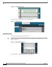
Step 1 Remove the module by pushing up on the handles to disengage from the lock notch. Once the handles
are disengaged, gently pull the handles out and slide the module out of the slot.
Step 2 To install a module, hold it so that the ejector handles are on the bottom.
Step 3 Pull the handles out to extend them. Slide the module into the appropriate slot of the chassis until it
makes contact with the backplane. As the module seats in the chassis, the handles will begin to close.
Step 4 Push the handles in to fully close.
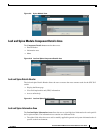
Hot Swapping the Fan Unit
Step 1 Loosen the captive panel screw.
Step 2 Pull the panel screw down to partially disengage the unit.
Step 3 Slowly pull the unit. The unit will disengage from the connector.
Step 4 Carefully slide the fan out until it is completely removed from its slot.
To install a fan unit:
Step 1 Place the unit into the slot. Slowly slide the fan unit in until it engages into the connector.
Step 2 Using the panel screw, push up to re-engage the unit.
Step 3 Tighten the captive panel screw.
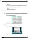
Hot Swapping Power Supplies
The SFS 7012 switch requires a minimum of three power supplies for normal operation. Power supplies
can be hot swapped without powering down the switch. To replace a power supply:
Step 1 Loosen the captive panel screw.
Step 2 Pull the panel screw down to partially disengage the unit.
Step 3 Slowly pull the unit. The unit will disengage from the connector.
Step 4 Carefully slide the power supply out until it is completely removed from its slot.
Step 5 To install a power supply:
Step 6 Place the unit into the slot. Slowly slide the power supply in until it engages into the connector.
Step 7 Using the panel screw, push up to re-engage the unit.