


22
Cisco uBR10-LCP2-MC16C/MC16E/MC16S Cable Interface Card for the Cisco uBR10012 Router
OL-2872-02
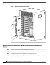
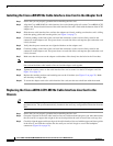
Removing and Replacing a Cisco uBR10-LCP2-MC16x Cable Interface Line Card
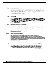
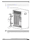
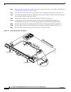
Figure 11 Closing the Ejector Levers
Connecting the Cables
When fully inserted, the cable interface line card cycles through its power-on self-test. The Power LED
comes on (green) and the Status LED comes on (yellow). If the card is operating correctly, the Status
LED then turns green. If these LEDs do not operate as described, refer to the “Troubleshooting the
Cisco uBR10-LCP2-MC16x Cable Interface Line Card” section on page 27 and the Cisco uBR10012
Universal Broadband Router Hardware Installation Guide at the following URL:
http://www.cisco.com/univercd/cc/td/doc/product/cable/ubr10k/ubr10012/hig/index.htm.
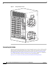
U
S
0
U
S
1
U
S
2
U
S
3
U
S
4
U
S
5
D
S
E
N
A
B
L
E
D
+42 dBmV
uBR-MC16C
U
S
0
U
S
1
U
S
2
U
S
3
U
S
4
U
S
5
D
S
E
N
A
B
L
E
D
+42 dBmV
uBR-MC16C
U
S
0
U
S
1
U
S
2
U
S
3
U
S
4
U
S
5
D
S
E
N
A
B
L
E
D
+42 dBmV
uBR-MC16C
U
S
0
U
S
1
U
S
2
U
S3
U
S
4
U
S
5
D
S
E
N
A
B
L
E
D
+42 dBmV
uBR-MC16C
U
S
0
U
S
1
U
S
2
U
S3
U
S
4
U
S
5
D
S
E
N
A
B
L
E
D
+42 dBmV
uBR-MC16C
U
S
0
U
S
1
U
S
2
U
S
3
U
S
4
U
S
5
D
S
E
N
A
B
L
E
D
+42 dBmV
uBR-MC16C
U
S
0
U
S
1
U
S
2
U
S
3
U
S
4
U
S
5
D
S
E
N
A
B
L
E
D
+42 dBmV
uBR-MC16C
U
S
0
U
S
1
U
S
2
U
S
3
U
S
4
U
S
5
D
S
E
N
A
B
L
E
D
+42 dBmV
uBR-MC16C
CISCO
10000
C
A
R
R
IE
R
A
L
A
R
M
L
O
O
P
F
A
IL
CH OC-12-DSO SM-IR
CISCO
10000
C
A
R
R
IE
R
A
L
A
R
M
L
O
O
P
F
A
IL
CH OC-12-DSO SM-IR
CISCO
10000
C
A
R
R
IE
R
A
L
A
R
M
L
O
O
P
F
A
IL
CH OC-12-DSO SM-IR
CISC
100
C
A
R
R
IE
R
A
L
A
R
M
L
F
A
IL
62453
ENABLED
U
S
1
U
S
0
ENABLED
U
S
1
U
S
0
ENABLED
U
S
1
U
S
0
ENABLED
U
S
1
U
S
0
D
S
0
uBR - MC28C
D
S
1
D
S
0
uBR - MC28C
D
S
1
D
S
0
uBR - MC28C
D
S
1
D
S
0
uBR - MC28C
D
S
1