


Preparing for Installation 2-13
Making a Crossover Ethernet Cable Connection
Making a Crossover Ethernet Cable Connection
The RJ-45 receptacle supports standard straight-through and crossover Category 5 UTP
(RJ-45) cables. Cisco Systems does not supply Category 5 UTP cables; these cables are
available commercially.
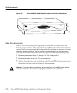
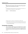
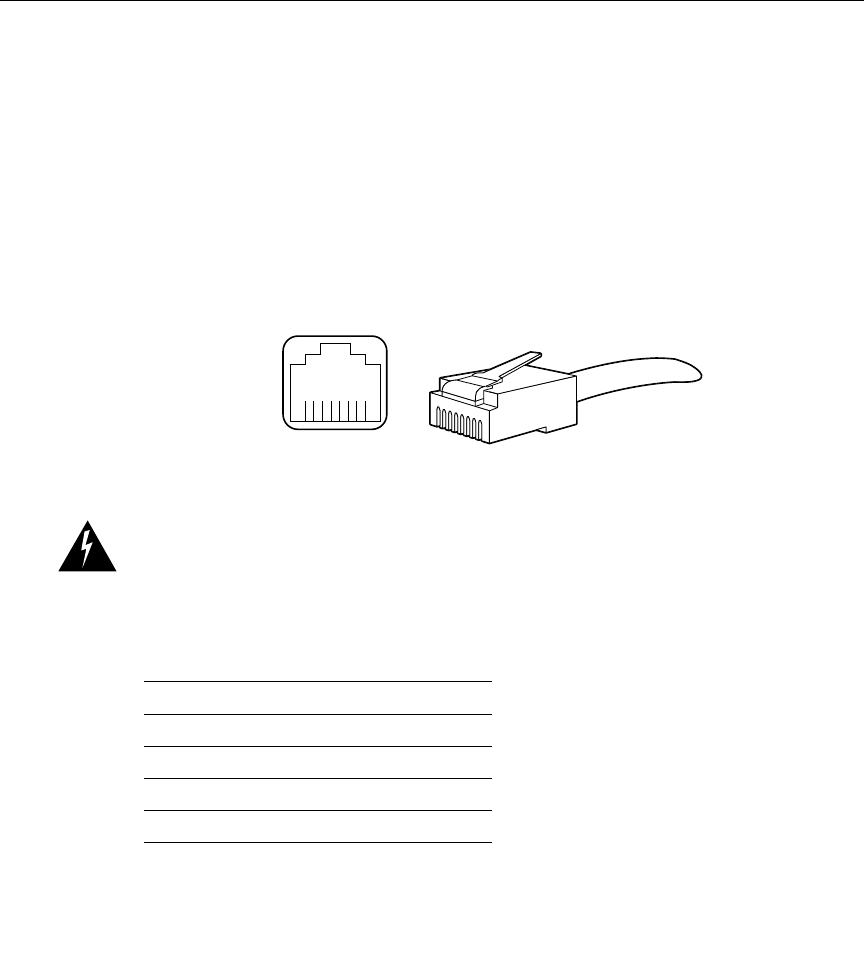
Figure 2-2 shows the RJ-45 receptacle and plug. Table 2-2 lists the pinouts and signals for
the RJ-45 receptacle.
Figure 2-2 RJ-45 Receptacle and Plug
Warning To avoid electric shock, do not connect safety extra-low voltage (SELV) circuits
to telephone-network voltage (TNV) circuits. LAN ports contain SELV circuits, and WAN
ports contain TNV circuits. Some LAN and WAN ports both use RJ-45 connectors. Use
caution when connecting cables.
Table 2-2 RJ-45 Receptacle Pinouts
Pin Description
1 Receive Data + (RxD+)
2 RxD–
3 Transmit Data + (TxD+)
6 TxD–
H2936
8 7 6 5 4 3 2 1
RJ-45 connector