


C-5
Catalyst 3750 Switch Hardware Installation Guide
OL-6336-07
Appendix C Connecting to DC Power
Connecting to DC Power
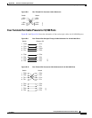
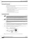
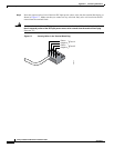
Step 3 Identify the positive and negative feed positions for the terminal block connection. The wiring sequence
is positive to positive and negative to negative for both the A and the B feed wires. The switch rear panel
identifies the positive and negative positions for both the A and B feed wires, as shown in Figure C-5.
Figure C-5 Positive and Negative Positions on the Switch Rear Panel
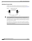
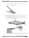
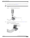
Step 4 Using a 18-gauge wire-stripping tool, strip each of the four wires coming from the DC-input power
source to 0.27 inch (6.6 mm) ± 0.02 inch (0.5 mm), as shown in Figure C-6. Do not strip more than 0.29
inch (7.4 mm) of insulation from the wire. Stripping more than the recommended amount of wire can
leave exposed wire from the terminal block plug after installation.
Figure C-6 Stripping the DC-Input Power Source Wire
132976
C
O
N
S
O
L
E
STACK 1
STACK 2
–
36 - 72V
3.0 - 1.5A
A
–
+
B
+
–
36 - 72V
3.0 - 1.5A
A
–
+
B
+
0.25 inch (6.3 mm)
±
0.02 inch (0.5 mm)
86460