


2-28
Catalyst 3750 Switch Hardware Installation Guide
OL-6336-07
Chapter 2 Switch Installation
Installing the Switch
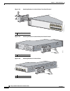
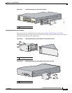
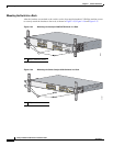
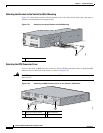
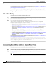
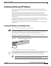
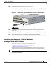
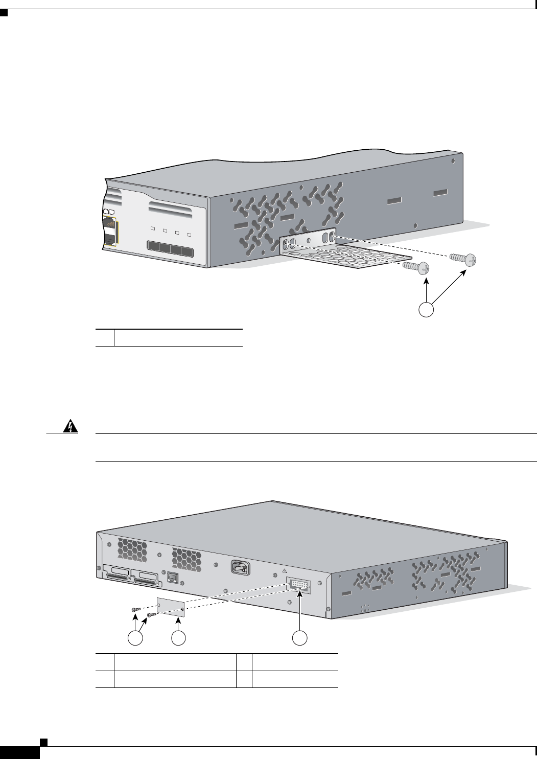
Attaching the Brackets to the Switch for Wall-Mounting
Figure 2-41 shows how to attach a 19-inch bracket to one side of the switch. Follow the same steps to
attach the second bracket to the opposite side.
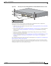
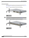
Figure 2-41 Attaching the 19-inch Brackets for Wall-Mounting
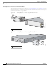
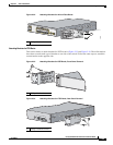
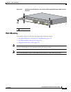
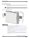
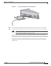
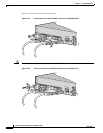
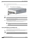
Attaching the RPS Connector Cover
If you are not using an RPS with your switch, use the two Phillips pan-head screws to attach the RPS
connector cover to the back of the switch, as shown in Figure 2-42.
Warning
If an RPS is not connected to the switch, install an RPS connector cover on the back of the switch.
Statement 265
Figure 2-42 Attaching the RPS Connector Cover on the Catalyst 3750 Switch
1 Phillips truss-head screws
Catalyst 3750
SERIES
2
3
X
2
4
X
2
3
2
4
25
26
27
28
1
86687
1 Phillips pan-head screws 3 RPS connector
2 RPS connector cover
C
O
N
S
O
L
E
STACK 1
STACK 2
D
C
I
N
P
U
T
S
F
O
R
R
E
M
O
T
E
P
O
W
E
R
S
U
P
P
L
Y
S
P
E
C
I
F
I
E
D
I
N
M
A
N
U
A
L
+
1
2
v
@
8
.
5
a
21 3
86571