


1-6
Catalyst 3750 Switch Hardware Installation Guide
OL-6336-07
Chapter 1 Product Overview
Front Panel Description
Gigabit Ethernet Switch Front Panel Descriptions
These sections describe the front panels for the Gigabit Ethernet switches:
• Catalyst 3750G-12S and Catalyst 3750G-12S-SD Switches Front Panel Description, page 1-6
• Catalyst 3750-24T, 3750G-24TS, and 3750G-24TS-1U Switches Front Panel Descriptions, page 1-6
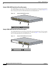
• Catalyst 3750G-48TS Switch Front Panel Description, page 1-8
• Catalyst 3750G-24PS Switch Front Panel Description, page 1-8
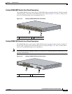
• Catalyst 3750G-48PS Switch Front Panel Description, page 1-9
• Catalyst 3750G-16TD Switch Front Panel Description, page 1-9
• Catalyst 3750G Integrated Wireless LAN Controller Switch Front Panel Description, page 1-10
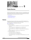
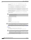
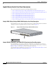
Catalyst 3750G-12S and Catalyst 3750G-12S-SD Switches Front Panel Description
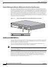
The SFP module slots on the Catalyst 3750G-12S and Catalyst C3750G-12S-SD switches are numbered
1 through 12. The slots are grouped in three sets of four, as shown in Figure 1-6.
Figure 1-6 Catalyst 3750G-12S and Catalyst 3750G-12S-SD Front Panel
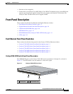
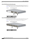
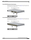
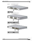
Catalyst 3750-24T, 3750G-24TS, and 3750G-24TS-1U Switches Front Panel Descriptions
The 10/100/1000 ports on the Catalyst 3750G-24T, 3750G-24TS, and 3750G-24TS-1U switches are
grouped in pairs. The first member of the pair (port 1) is above the second member (port 2), as shown in
Figure 1-7, Figure 1-8, and Figure 1-9. Port 3 is above port 4, and so on.
The SFP module slots are numbered 25 to 28 on the Catalyst 3750G-24TS Front Panel (Figure 1-8) and
on the Catalyst 3750G-24TS-1U Front Panel (Figure 1-9).
1 SFP module slots
C
a
t
a
l
y
s
t
3
7
5
0
S
E
R
I
E
S
S
Y
S
T
R
P
S
M
A
S
T
R
S
T
A
T
D
U
P
L
X
S
P
E
E
D
S
T
A
C
K
M
O
D
E
4
1
2
3
1
2
9
1
0
1
1
8
5
6
7
1
97166