


1-14
Catalyst 3850 Switch Hardware Installation Guide
OL-26779-02
Chapter 1 Product Overview
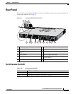
Front Panel
ACTV LED
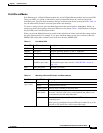
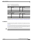
STACK LED
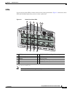
The STACK LED shows the sequence of member switches in a stack. Up to four switches can be
members of a stack. The first four port LEDs show the member number of a switch in a stack. Figure 1-5
shows the LEDs on the first switch, which is stack member number 1. For example, if you press the Mode
button and select Stack, the LED for port 1 blinks green. The LEDs for ports 2 and 3 are solid green, as
these represent the member numbers of other switches in the stack. The other port LEDs are off because
there are no more members in the stack.
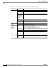
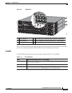
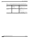
Blinking Green This appears on the switch in a StackPower ring configuration
that detects an open ring or has only one StackPower cable
connected.
Amber There is a fault: load shedding is occurring, a StackPower cable
is defective, or administrative action is required. See the switch
software configuration guide for information about configuring
StackPower.
Blinking Amber The StackPower budget is not sufficient to meet current power
demands.
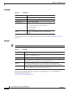
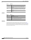
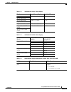
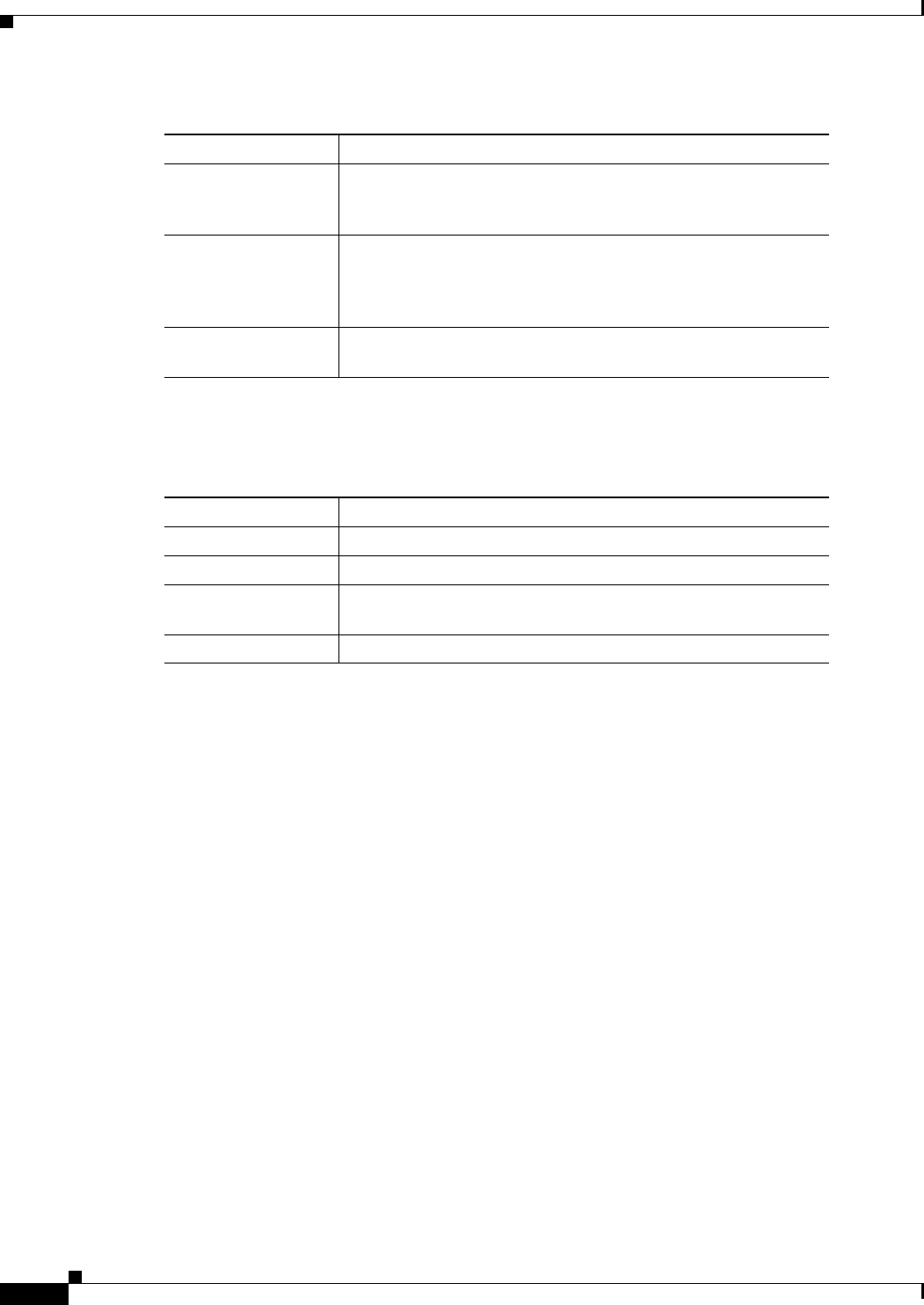
Table 1-9 ACTV LED
Color Description
Off Switch is not the active switch.
Green Switch is the active switch or a standalone switch.
Amber An error occurred when the switch was selecting the active
switch, or another type of stack error occurred.
Slow blinking green Switch is in stack standby mode.
Table 1-8 S-PWR LED
Color Description